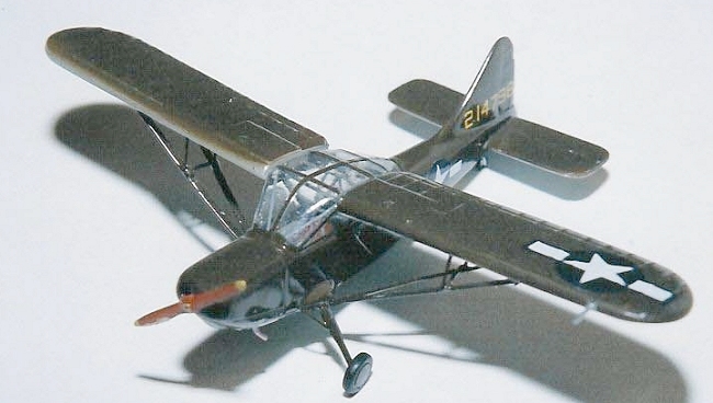
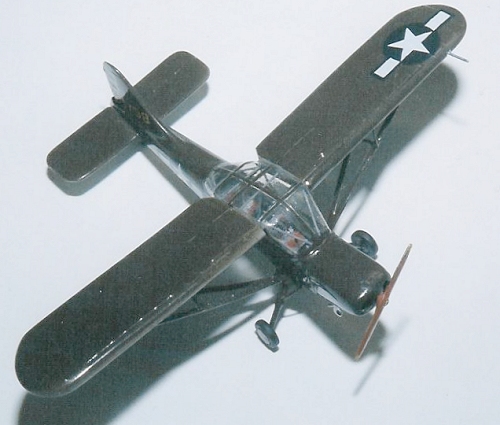
Beechnut 1/72 Stinson L-5 Sentinel
| KIT #: | ? |
| PRICE: | $+/- $20 back in the previous century |
| DECALS: | basic insignia |
| REVIEWER: | Joel Hamm |
| NOTES: | Early cottage industry kit |
| HISTORY |
Even aficionados of
short-run kits may scratch their heads at mention of the name Beechnut.
This company was essentially a one-man-show (according to the owner) that
flourished briefly, along with Merlin, Pegasus, Meikraft, 12 Squared and a
few 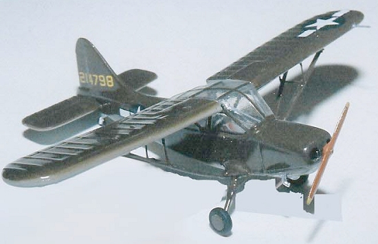 others, during the heyday of the back-yard model-molding era. Only one
(Pegasus) of these endeavors survives (barely), but their philosophy of
supplying to styrene addicts subjects besides Messerschmits and Mustangs
has happily been adopted by a consortium of Czech companies which have
since issued their own high quality, resin and PEB embellished but short
run injection moldings of these pioneer’s early offerings.
others, during the heyday of the back-yard model-molding era. Only one
(Pegasus) of these endeavors survives (barely), but their philosophy of
supplying to styrene addicts subjects besides Messerschmits and Mustangs
has happily been adopted by a consortium of Czech companies which have
since issued their own high quality, resin and PEB embellished but short
run injection moldings of these pioneer’s early offerings.
Anyone who wants to know about history or technical specs need only Google on “Stinson L-5”, or pick up a copy of the referenced book. Suffice it to say that the “Flying Jeep” was the most widely used liaison aircraft in WWII or Korea, served in every theater, and participated in some hair-raising adventures and hare-brained (yet successful) schemes, such as the Brodie System of launching and recovering from a wire. Two versions were produced: the A Model was a more-or-less bubble-top, or as Cessna Aircraft called its wrap-around windshields – “Omni vision” observation platform. The B was a razorback ambulance with no rearward greenhouse.
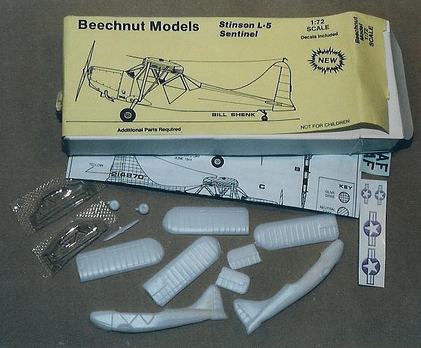
| THE KIT |
 This
rendering represents the observer plane. A very plain box with stick-on
label contains the bare bones, which the builder must flesh out using
skill, ingenuity, patience, persistence, and a well stocked parts box.
Molded in thick, white, somewhat soft plastic are 2 fuselage halves, 4 wing
pieces, 2 tailplanes, a pair of misshapen wheels, and a barely recognizable
propeller. The transparencies come as a split vacu-form. Instructions are
a single page diagram with stencils for making struts, gear legs, and other
DIY doo-dads. A decal sheet of 4 US insignia is uselessly off color, out
of register, and out of focus. Out of your mind is how you think you must
be to tackle this project, but challenge is the appeal of these kits. On
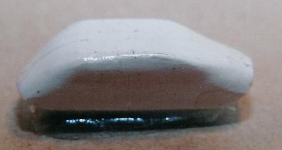
the plus side, surface detail is crisp. On the minus side, most of it must
be ground away to correct contour problems, particularly on the airfoils.
The molding technique, whatever it may have been, resulted in thick panels
with an exaggerated camber. Thinning the underside can do just so much
before the chord gets whittled away. The modeler has 2 choices: re-shape
the surface side and replace lost detail, neither of which is easy in this
soft plastic; or accept the deformity and avoid looking too closely at
trailing edges, where the departure from reality is most acute.
This
rendering represents the observer plane. A very plain box with stick-on
label contains the bare bones, which the builder must flesh out using
skill, ingenuity, patience, persistence, and a well stocked parts box.
Molded in thick, white, somewhat soft plastic are 2 fuselage halves, 4 wing
pieces, 2 tailplanes, a pair of misshapen wheels, and a barely recognizable
propeller. The transparencies come as a split vacu-form. Instructions are
a single page diagram with stencils for making struts, gear legs, and other
DIY doo-dads. A decal sheet of 4 US insignia is uselessly off color, out
of register, and out of focus. Out of your mind is how you think you must
be to tackle this project, but challenge is the appeal of these kits. On
the plus side, surface detail is crisp. On the minus side, most of it must
be ground away to correct contour problems, particularly on the airfoils.
The molding technique, whatever it may have been, resulted in thick panels
with an exaggerated camber. Thinning the underside can do just so much
before the chord gets whittled away. The modeler has 2 choices: re-shape
the surface side and replace lost detail, neither of which is easy in this
soft plastic; or accept the deformity and avoid looking too closely at
trailing edges, where the departure from reality is most acute.
| CONSTRUCTION |
Starts with opening up and cleaning out the engine intakes. These are not quite accurate, lacking the “flared nostrils” look of the real thing. You can try re-sculpting the cowl with filler or super-gel, but neither bonds well enough with this plastic to be seemlessly sanded to shape. I painted the openings black then plugged them with cast metal cylinders scrounged from an Aeroclub after-market radial. Other holes, for the exhaust stubs and intake pipe, are best drilled at this stage. Pilot and passenger doors are erroneously scribed on the left side, so they must be filled and re-scribed on the right.
 The fuselage mating surfaces must be
flattened by sanding against a flat sheet of 220 grit; but even after
thinning to the max the vertical tail still sticks out like a sore thumb.
As a matter of fact, a thumb is exactly what it resembles – or perhaps a
1/72 scale tomb stone. In any event, it was so grossly oversize as to
threaten continuation of the kit. The solution was to perform a rudder-ectomy
, re-shape the fin, and replace the control surface with a piece of
elevator from the spares bin (I think it came from one of the Monogram or
Matchbox bipes). That treasure box would not yield equally acceptable
alternates for the horizontal tail, so those slab-like planes were thinned
and re-scribed, receiving new ribs made of evergreen strips. The results
would win no awards at an IPMS Grand-Nationals show, which is why the
surgery was performed on the under surfaces only.
The fuselage mating surfaces must be
flattened by sanding against a flat sheet of 220 grit; but even after
thinning to the max the vertical tail still sticks out like a sore thumb.
As a matter of fact, a thumb is exactly what it resembles – or perhaps a
1/72 scale tomb stone. In any event, it was so grossly oversize as to
threaten continuation of the kit. The solution was to perform a rudder-ectomy
, re-shape the fin, and replace the control surface with a piece of
elevator from the spares bin (I think it came from one of the Monogram or
Matchbox bipes). That treasure box would not yield equally acceptable
alternates for the horizontal tail, so those slab-like planes were thinned
and re-scribed, receiving new ribs made of evergreen strips. The results
would win no awards at an IPMS Grand-Nationals show, which is why the
surgery was performed on the under surfaces only.
Lack of any locating slots or tabs means that frequent dry-fitting, filing, and fiddling are required to get all attachment angles and positions right. An instant but adjustable glue “grab” can be gotten by first softening each surface with liquid (Ambroid, Plastruct, Acetone, MEK, purple PVC pipe primer...) then applying a bead of more viscous stuff. Testors Liquid Cement is a best bet.
Wing panel halves were thinned as much as possible, also on the undersides, then glued together with the 2 part cement system. The kit was not really worth the trouble of re-shaping and re-surfacing, so the don’t-look-too-hard option was adopted, allowing a rapid progression to the most challenging feature – the canopy.
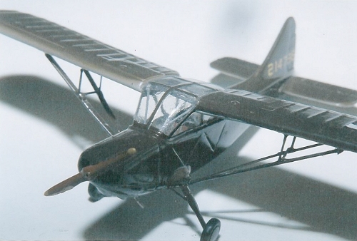
 “Greenhouse effect” is the focal point of a plane like this, but the
kit-supplied vacu-halves were two different sizes and shapes. Using them
as female molds I cast new male plugs with Durham’s Rock Hard Wood Putty. I
sanded these to a mating size and shape and sucked replacements on a
stove-top vacu-forming rig (*). Getting them to stick together was still a
problem. A one piece canopy would be ideal, but didn’t seem vacu-formable,
since it would have an inverted flask shape, with the closed end wider than
the opening. I didn’t think heated acetate could be coaxed into a stunt
like that, but a few test shots showed I was wrong. If you find the right
clear stuff, get it hot enough, apply enough vacuum, and think only happy
thoughts, you can indeed get it to stretch then shrink back on itself
without creasing or folding. The problem of getting the foming plug out is
no problem at all if you use plaster of Paris, which can be dissolved
and/or drilled out of the narrow-necked form.
“Greenhouse effect” is the focal point of a plane like this, but the
kit-supplied vacu-halves were two different sizes and shapes. Using them
as female molds I cast new male plugs with Durham’s Rock Hard Wood Putty. I
sanded these to a mating size and shape and sucked replacements on a
stove-top vacu-forming rig (*). Getting them to stick together was still a
problem. A one piece canopy would be ideal, but didn’t seem vacu-formable,
since it would have an inverted flask shape, with the closed end wider than
the opening. I didn’t think heated acetate could be coaxed into a stunt
like that, but a few test shots showed I was wrong. If you find the right
clear stuff, get it hot enough, apply enough vacuum, and think only happy
thoughts, you can indeed get it to stretch then shrink back on itself
without creasing or folding. The problem of getting the foming plug out is
no problem at all if you use plaster of Paris, which can be dissolved
and/or drilled out of the narrow-necked form.
 That’s
exactly what I did, casting plaster plugs in my replacement canopy
halves. The two sections were white-glued together, fit onto the fuselage
and tweaked to final shape with dabs of additional plaster and careful
filing. The first vacu-attempt yielded a perfect one-piece transparency
custom fit to the cockpit opening. The plaster plug was left in place to
facilitate framing, performed with strips of Pactra Trim-tape coated with
Future (*). A few drops of vinegar softened the plaster so it could be
drilled and diggled out. Interior bracing struts were added using
stretched sprue and CA.
That’s
exactly what I did, casting plaster plugs in my replacement canopy
halves. The two sections were white-glued together, fit onto the fuselage
and tweaked to final shape with dabs of additional plaster and careful
filing. The first vacu-attempt yielded a perfect one-piece transparency
custom fit to the cockpit opening. The plaster plug was left in place to
facilitate framing, performed with strips of Pactra Trim-tape coated with
Future (*). A few drops of vinegar softened the plaster so it could be
drilled and diggled out. Interior bracing struts were added using
stretched sprue and CA.
The fuselage and wings were painted and decaled, then the canopy was joined using white glue, which also caulked and faired the few remaining gaps. Instructions called for stiffening the wing installation with wire spars through the canopy, but plastic-bonding epoxy provided a strong wing joint without the prosthesis. To get and hold the correct angles I made a jig out of a Panavise Jr. and strips of aluminum cut from a pie tin.
| COLORS & MARKINGS |
 Diagrams are
provided for four aircraft but decals for none. Overall silver was out, not
only because it highlights all the flaws, but because the Stinson would be
joining a shelf-full of other civilians drafted into Army OD (just like
lots of us). Accepted painting practice is to use exotic imported acrylic,
factory-formulated from the original FS-recipes. This must be gloss coated
(Future – what else) to accept decals, which in turn must be glossed over,
then the whole she-bang flattened with a high tech, high price optical
dispersant. Don’t believe none of it! Nothing is as easy to use, or
performs as well as those little bottles of Testors Enamel from Wal-Mart or
the corner “iron mongery” (remember when they were 10 cents a botttle?)
Thin with Testors Airbrush Solvent and use a misting of Future to tone down
the sheen to an accurate scale representation of “non-specular”. Yes, I
realize this is a subject arousing blazing passion among modelers, so I
have appended a postal address for receiving hate mail and death threats.
Mailing actual IED’s, remember, is illegal – it says so right on the Post
Office drop box. Anyhow – critics are correct to point out that camo
colors are not available in gloss; however they can easily be concocted
from available enamels using reference paint chips, which are standard
appendix to most “Color and Marking” tomes. In the case of Army OD (which
spanned a wide chromatic spectrum) start with bright green, add some brown,
and a dollop of orange to seg it to the Khaki side of Marine Green.
“Scale effect” is another of those subjects that can get you kidnapped and
decapitated by a gang of fuming Federal Standard fundamentalists, but
lightening, or rather brightening, the final color actually does look more
real on the shelf than the real thing.
Diagrams are
provided for four aircraft but decals for none. Overall silver was out, not
only because it highlights all the flaws, but because the Stinson would be
joining a shelf-full of other civilians drafted into Army OD (just like
lots of us). Accepted painting practice is to use exotic imported acrylic,
factory-formulated from the original FS-recipes. This must be gloss coated
(Future – what else) to accept decals, which in turn must be glossed over,
then the whole she-bang flattened with a high tech, high price optical
dispersant. Don’t believe none of it! Nothing is as easy to use, or
performs as well as those little bottles of Testors Enamel from Wal-Mart or
the corner “iron mongery” (remember when they were 10 cents a botttle?)
Thin with Testors Airbrush Solvent and use a misting of Future to tone down
the sheen to an accurate scale representation of “non-specular”. Yes, I
realize this is a subject arousing blazing passion among modelers, so I
have appended a postal address for receiving hate mail and death threats.
Mailing actual IED’s, remember, is illegal – it says so right on the Post
Office drop box. Anyhow – critics are correct to point out that camo
colors are not available in gloss; however they can easily be concocted
from available enamels using reference paint chips, which are standard
appendix to most “Color and Marking” tomes. In the case of Army OD (which
spanned a wide chromatic spectrum) start with bright green, add some brown,
and a dollop of orange to seg it to the Khaki side of Marine Green.
“Scale effect” is another of those subjects that can get you kidnapped and
decapitated by a gang of fuming Federal Standard fundamentalists, but
lightening, or rather brightening, the final color actually does look more
real on the shelf than the real thing.
Specific markings were determined by what decals dropped out of the spares box, and what reference photos could be found. D Day invasion stripes were another more-trouble-than-the-kit-is-worth option, so I settled for reproducing an L-5 featured on one of the Smithsonian NASM web pages. An interesting oddity was the serial number clearly depicted on the port wing underside. Well, if the National Air & Space Museum says it was there, damned if I’m going to argue. Cutting and sticking individual tail numbers from a Microscale (now Superscale) sheet took several sessions, since it’s best for eyesight as well as adhesion to set only a few at a time.
| FINAL CONSTRUCTION |
 Wing struts
were fabricated from Plastruct Strut Extrusions (try saying that three
times fast) laid out on the instruction sheet diagram. Two tricks: Xerox
the sheet so you can do both at once. Swipe the diagram with a water
soluble glue stick, such as UHU, to hold the pieces in place while the glue
dries. Landing gear struts could have been made from pulled sprue, but I
found a set of perfectly shaped ones in the spares box. I believe they
belonged to a landplane version of the Airfix Kingfisher. Wheels also came
from the parts bin. The flat disc hubcaps were punched out of thin sheet
using a hollow gasket punch. Hint: paint the sheet first – this saves
masking. Other fiddledybits were made from sprue, or wire. A replacement
prop just would not materialize (not many subjects came with fixed pitch
wooden 2-blade) so the kit prop was re-shaped to a reasonable facimile,
reasonableness enhanced by an etched brass hub, which really isn’t a hub,
but is too small to determine otherwise.
Wing struts
were fabricated from Plastruct Strut Extrusions (try saying that three
times fast) laid out on the instruction sheet diagram. Two tricks: Xerox
the sheet so you can do both at once. Swipe the diagram with a water
soluble glue stick, such as UHU, to hold the pieces in place while the glue
dries. Landing gear struts could have been made from pulled sprue, but I
found a set of perfectly shaped ones in the spares box. I believe they
belonged to a landplane version of the Airfix Kingfisher. Wheels also came
from the parts bin. The flat disc hubcaps were punched out of thin sheet
using a hollow gasket punch. Hint: paint the sheet first – this saves
masking. Other fiddledybits were made from sprue, or wire. A replacement
prop just would not materialize (not many subjects came with fixed pitch
wooden 2-blade) so the kit prop was re-shaped to a reasonable facimile,
reasonableness enhanced by an etched brass hub, which really isn’t a hub,
but is too small to determine otherwise.
| CONCLUSIONS |
Lots of shortcomings. Lots of work. Chance to develop some useful techniques. Not a bad representation, as long as you’re not anal about exactness. The usual consolation can’t be used: that this is the only version likely to emerge in injected incarnation. One of the Czech companies, I believe it was Sword, put out an L-5 (possibly the ambulance “B” model, this one is the observation L-5A) that got bad reviews for its poor quality injected transparencies. If I can find one I’ll modify it with a one-piece blown bubble and let everyone know how it worked out.
March 2005
| REFERENCES |
L-Birds, Terry M. Love Flying Books International 2001, Plus tons of stuff on the Web.
FOOTNOTE (*): If anyone would like copies of articles on an easy-to-build-and-use a vacu-form rig, and on this canopy framing technique, please E-mail me your postal address.
Copyright ModelingMadness.com. All rights reserved. No reproduction in any form without express permission from the editor.
If you would like your product reviewed fairly and fairly quickly, please contact the editor or see other details in the Note to Contributors.