|
KIT # |
PX 023 |
|
PRICE: |
£ 12.00 |
|
DECALS: |
One aircraft |
|
REVIEWER: |
Mats Olsson |
|
NOTES: |
Vacuform kit with metal accessories |
|
HISTORY |
Awe is the sentiment that dominates when you study the development and features of the XF-91. The ingenuity and engineering skills of the Republic team were truly amazing, creating such an advanced and formidable piece of machinery in the late ´40s.
The US military command had, already late in the war, envisioned a future bomber-threatfrom Soviet Russia(that was inevitably going to develop nuclear-bomb capacity before long). (The truth in this matter was, with hindsight, that the Russians didn´t have a long-range bomber-fleet until 1949-50, equipped only with the painstakingly copied B-29, the Tu-4 Bull.)
In response to this possible threath Secret Project No. MX-809 was created, proposing a high speed, high altitude daytime interceptor aircraft capable of ”meeting and defeating any strategic bomber aircraft that any potential adversary might produce”. The Special Operational Requirement(SOR) included that the airplane was to be capable of 25.5 min. combat operation, divided into: 2.5 min. to climb to 47.500feet(19.000feet/min); 15 min. cruise time at 486knots indicated air speed; 3 min. of combat duration at an average of 688 kias; 5 min. of descent time from 47.500 feet to landing. These were very tough requirements indeed, given the technical level of the day. 688 knots average combat speed meant supersonic performance, climb-rate demands indicated rocket-power!
Alexander Kartveli himself led the Republic design team that on May 29, 1946 got the contract to produce two prototypes of the company´s proposed AP-31 model(Convair simultaneously recieved a contract for their model 7, that was to become the XF-92, fore-father of the F-102/106 family).
The AP-31, now designated XP-91, was a tour-de-force of aircraft engineering: Twin powerplants, turbojet+rockets, afterburner, swept wings with inverse taper and variable incidence and different tail & nose configurations along the way.
The Republic team studied reports of the German Me 163 Komet rocket interceptor and the Me 262C Heimatschutzer, the latter combining turbojet/rocket power, to gain information on the planned propulsion system. The General Electric J47-GE-3(substitution for the planned GE-7, not yet available) was to be combined with the projected Curtiss Wright XLR-27-CW 1 four-chamber rocket motor, theoretically giving the Thunderceptor a top-speed of Mach 2 with everything burning.
The CurtissWright, however, was never to become reality and the rocket unit was replaced by the tried-and-true XLR-11-RM-9 from Reaction Motors. This was identical to the unit that pushed Chuch Yeager and the Bell X-1 through the sound-barrier on Oct.14, 1947.
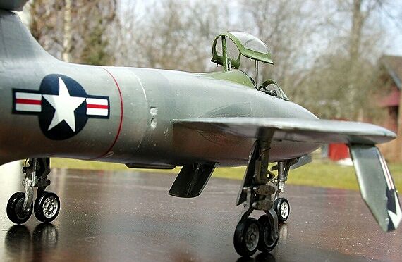
The XF-91(P changed to F when the prefix system was revised in June 1948) began flight tests at Muroc AFB on 9 May 1949, first flying with Carl Bellinger at the controls. Throughout flight testing the XF-91 performed brilliantly and most of the advanced ideas from the drawing board also worked well in the air. The inverse-taper wing, that was adopted to eliminate the risk of wing-tip stall, a serious problem for first-generation swept-wing aircraft, worked out just as planned. The thin, narrow wing-root inevitably stalled first, with a fully controllable nose-down pitching as a result.
 The thin inner wing proposed another
problem for the engineers: where to put the undercarriage? The solution was a
highly original arrangement with bicycle-style twin main-wheels(looks like a
Viggen!) retracting outwards into the wingtips.
The variable incidence of the wing( -2 to
+6 degrees) was also tested to good advantage, designed to enhance behaviour at
takeoff and landing. These features combined gave the Thunderceptor a very broad
speed-range and safe handling in all registers.
During the first three years of flight
testing the XF-91 was powered by the J47 alone and the first rocket motor wasn´t
installed until Nov. 1952.
The thin inner wing proposed another
problem for the engineers: where to put the undercarriage? The solution was a
highly original arrangement with bicycle-style twin main-wheels(looks like a
Viggen!) retracting outwards into the wingtips.
The variable incidence of the wing( -2 to
+6 degrees) was also tested to good advantage, designed to enhance behaviour at
takeoff and landing. These features combined gave the Thunderceptor a very broad
speed-range and safe handling in all registers.
During the first three years of flight
testing the XF-91 was powered by the J47 alone and the first rocket motor wasn´t
installed until Nov. 1952.
Bellinger was the first to take the XF-91 through the sound-barrier, in a 30 degree dive and on turbojet power only and on the 9th December 1952, Russel ”Rusty” Roth hit Mach 1.07 in level flight with two of the four rocket-chambers burning. This date marks the first soun-barrier-breaking flight of an American combat aircraft in level flight. With all five powerplants in action the XF-91 achieved a maximum speed of Mach 1.71! That´s fast for the early ´50s!
Originally proposed armament for the Thunderceptor was four nose-mounted 20mm cannon and other suggested configurations were different rocket-launchers in retractable bellymounts and a later variant proposal with a rocket-nose. During the later stages of development different tail- and nose configurations were tested. A Vee-butterfly tail and a radar nose were tried in different combinations on the two prototypes that were built.
However well the Thunderceptor performed, this was a time when things changed rapidly. Technical advances, turbojet development and new concepts of the typical interceptor mission combined with a lengthy test-period and cumbersome ground-handling due to the dual-propulsion system(refuelling and handling of the rocket-units alone required a specially designed truck, manned by ”space-men” in asbestos suits) made the XF-91 obsolete even before it´s first flight.
With the advent of a new proposal from the Air Force, the ”1954 All Weather Interceptor” (1954 optimistically indicating the year when such an aircraft would be in service) and new concepts and requirements given for such an aircraft, Republic entered with three designs of which one was a Thunderceptor derivative designed XF-91B. This project, however, never became a serious contenter for an Air Force contract.
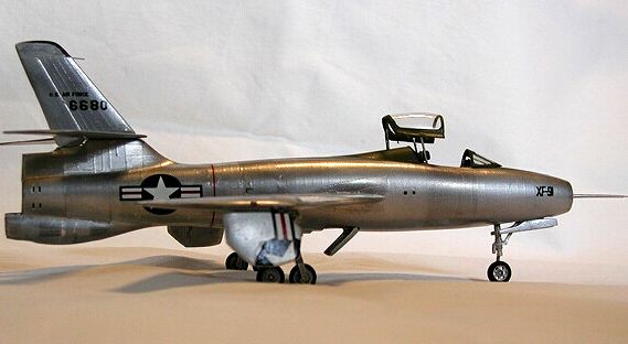
On the 6th anniversary of it´s first flight 6680, the first prototype, was shipped to the Air Force Museum in Dayton, where it can be seen today, in a radar-nosed configuration. The second prototype was used for firefigther crash-rescue training and was eventually destroyed.
Late input (April 2005) "Just read your review of the XF-91 kit. Your information has an error. The second prototype, 46-681 was not used for fire-fighting training but was destroyed in a crash in the summer of 1951 when the engine suffered a catastrophic failure on take-off from Edwards AFB dry lakebed in a test flight flown by Carl Bellinger. In Chuck Yeager's autobiography, "Yeager" (Bantam, 1985) the incident is recounted on pages 189-190. As the aircraft lifted off and Bellinger retracted the landing gear, Yeager, flying chase in an F-86, radioed that the engine was coming out the exhaust. Bellinger put it down immediately and exited the aircraft as the tail melted off. By the time the fire equipment arrived from seven miles away the airframe was ashes. Time from lift-off to the pilot exiting the XF-91 was 90 seconds." ----- Mark Sublett
The Thunderceptor was a remarkable feat of aeroplane design and engineering and provided much valuable information and experience for it´s contemporary F-84 family as well as the later Republic success-story, the F-105 Thunderchief. Many see the Thunderceptor as an ugly, oddball beast, the ”flop-eared mule”, when it in reality was a sleek, well behaved racer, too advanced and complicated for regular Air Force service in a time when airplane technology raced ahead into the jet-era.
|
THE KIT |
If Bill Koster is Mr. vacform-Tamiya, then surely Gordon Stevens must be Mr. vac-Hasegawa. He´s the designer behind those great Rareplanes kits and some of the Maintrack Project-X line that this kit comes from, the XF-91 being one of his works.
Kit includes parts to build all variants of the XF-91 with the different nose/tail/rocket configurations and two sets of different drop-tanks. It also includes, and this is most satisfying, beautifully cast metal undercarriage units. This part of the Thunderceptor is a very complex affair and a real challenge if you were to scratchbuild them. Also included are decals, thank you, as you´re not likely to find any aftermarket sheet for this one(to be honest, the only items exclusive to this decal sheet are the XF-91 logos and the tail numbers, stars ´n bars and USAF letters shouldn´t be too impossible to find).
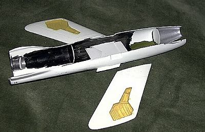
 Panel lines are extremely delicate, to the
point that you worry if it can even take the thin layer of natural metal finish
required. The ”multi-faceted” paneling on the fuselage is especially well
captured and is noticeable from certain angles only, just like on the real
thing. Very impressive handicraft!( Please compare
with the Lindberg 1/48 ”riveteers-wet-dream” of a kit! Talk about two ends of a
spectrum!!) The only flaw I could find were a number of
small pips from the moulding-process. These should, however, be possible to
remove with a new X-acto blade and a steady hand. Well, I hope so!
Panel lines are extremely delicate, to the
point that you worry if it can even take the thin layer of natural metal finish
required. The ”multi-faceted” paneling on the fuselage is especially well
captured and is noticeable from certain angles only, just like on the real
thing. Very impressive handicraft!( Please compare
with the Lindberg 1/48 ”riveteers-wet-dream” of a kit! Talk about two ends of a
spectrum!!) The only flaw I could find were a number of
small pips from the moulding-process. These should, however, be possible to
remove with a new X-acto blade and a steady hand. Well, I hope so!
Also included, as metal items, are jet-pipe, alternative rocket-exhaust and different nose-probes. A metal seat is also included but seems to be thrown in for good measure only as it has no resemblance to the real seat of the airplane( it looks like an Aeroclub MB-seat of some sort and can always be a good addition to the spares-box). One vacuformed canopy means no forgiveness for a slippery knife.
Instructions are the usual exploded view of the kit and directions on how to cut out and assemble. You also get the 1/72 scale drawing( as always with Rareplanes/Maintrack) that, in my own humble opinion, should be standard in all kits. Very helpful! Painting is very briefly described(and wrong: fuselage trim/walkways should be olive drab, not ”greyish black”) and there is also a short history/ref.listing.
Rareplanes and Maintrack are like Santa Claus to us who are obsessed with everything starting with X, XP- or XF. The Project-X line includes goodies like the XF-88, XF-90 and F-107, among others, all in the one and only true scale of 1/72J Good quality vacuform-kits that have all the basic elements to make true models of unusual, not-so-middle-of-the-road, subjects.
Other kits of the XF-91 are the dreadful 1/48 Lindberg issue, riveted to the hilt, making all those early Airfix kits green with envy (but please, pay a visit to the ARC website and take a look at Rodney Williams overhaul of this kit. Goes to show what can be done with any old box of garbage if you only have the talent and some 1.600 hours of spare time for modeling. Incredible work!!). There is also a very plain vacform in 1/72 from KR-models(long gone) and possibly a Merlin kit(if you count them?)
|
CONSTRUCTION |
I had decided to add some detail to this kit and laid out a plan for scratchbuilding parts or, if possible, borrow from other suitable models( F-84 family). I soon arrived at a quite drastic, or at least rather expensive, decision: robbing parts from the Tamiya F-84G! Well, I had bought a couple of them and realized that I couldn´t get a better cockpit from anywhere else. I test fitted the parts loosely and found out they would actually fit right in the vac-kit.
Maybe the nose-gear bay/intake-splitter? Sorry, the XF-91 gear retracts forward, thus excluding the Tamiya part(F-84 gear retracting backwards). After some scrounging around in various F-84 kit-boxes(=Italeri and Heller) I finally got hold of an Italeri F-84F( thank you Erwin S.) that had a very plain nose gear bay/intake-splitter part that fit just fine(=same scale!) in the Maintrack kit. The gear bay had no detail to it, making it the perfect victim of my own surgical daydreaming.
Then there is the choice of what version of the Thunderceptor you want to model? Rollout? Radar-nosed? Vee-tail? Rocket-configuration? Two aircraft were built and they were both given various configurations throughout flight-tests. I finally settled on 6680 that took the lions-part of the tests and I also decided to go for the configuration used at approx. the time of the sound-barrier-breaking flights. This meant revising the rocket-fairings under the rear fuselage, more on this later in construction.
You can go two ways when you start on a vacuform kit. Either you take the bull by the horns and cut out, sand and prepare all the parts in one go, or you take the sub-assemblies one by one, wings, fuselage and so on, and work on them one at a time. Most of the time the latter method is nicer since you won´t have to do all that boring sanding in one take. Sometimes, however, you need to have all major parts available at the same time to be able to plan, dryfit and adapt parts as you go on.
 In the case of the XF-91 I chose the tough
way as I was intending to do a lot of ”special”
arrangements(scratch-build gear-wells,
adapt parts from other kits and generally mess around with the basic kit) and so
needed all parts prepared from the start. I
use
sandpaper stretched over a plastic cutting-board for the sanding down on
kit-parts. This way I always have a convenient ”edge”
to sand over as I turn the board around for the best sanding angle. This is
especially handy with smaller parts that are impossible to hold flat
down to the sandpaper. You need the edge of
the board so you can hold the kit-part ”outside”
of it. Once all parts were cut out and sanded I
started removing the moulding-pips with the tip of a brand new X-acto blade.
This operation seemed to work quite well, but there´s no telling really how
succesful I had been until painting/finishing time.
In the case of the XF-91 I chose the tough
way as I was intending to do a lot of ”special”
arrangements(scratch-build gear-wells,
adapt parts from other kits and generally mess around with the basic kit) and so
needed all parts prepared from the start. I
use
sandpaper stretched over a plastic cutting-board for the sanding down on
kit-parts. This way I always have a convenient ”edge”
to sand over as I turn the board around for the best sanding angle. This is
especially handy with smaller parts that are impossible to hold flat
down to the sandpaper. You need the edge of
the board so you can hold the kit-part ”outside”
of it. Once all parts were cut out and sanded I
started removing the moulding-pips with the tip of a brand new X-acto blade.
This operation seemed to work quite well, but there´s no telling really how
succesful I had been until painting/finishing time.
The XF-91 kit is divided into four main sub-assemblies, fuselage, wings, tailplane and fin and I started with the wings. With kit-parts sanded out, I boxed in the wheel-wells with strips of styrene, CA-glued to the bottom wing and sanded down to fit flush to the upper wing-half. Wing-halves were then glued together(with regular Humbrol plastic cement) and wheel-well joints were puttied/sanded and cleaned up. I detailed the wells according to what photos I had available for this region, no complete references, unfortunately. Stringers in the well-roof were fashioned from narrow, doubled strips of auto-masking-tape. Additional detail came from Contrail-rod, thin styrene and fine electrical wire. I also installed short lenghts of brass-tubing to act as gear posts, more on this later.
Wings were now set aside and up on the assemby line roll tailplanes and fin( you can probably already sense my avoiding the ”big one”, the fuselage, the dreaded, fearsome, long joint under a natural-metal finish, huh… I´m shuddering. ”The big one” makes me think of a Neil Young tune where there´s a line going ”..he caught the big one but he let it go..”, which is about surfing but could also apply to my modeling; I caught the big Lindberg kit of the Thunderceptor, but I let it go!)
Enough time-wasting! Tailplanes come in two halves, top/bottom for the whole thing, left and right. The fin goes on top of this, thus making the entire assebly into a very fragile construction as everything is supposed to be butt-joined. Plugs were needed to strengthen this area and I drilled out holes for a couple of paper-clip posts to go from the fin, through the tailplane and down into the fuselage.
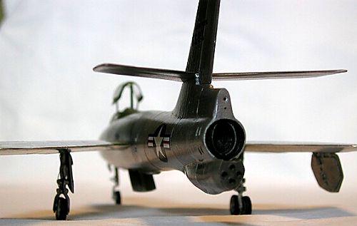
I relaxed a bit, assembling and painting the Tamiya cockpit. What kits they make!( I had almost forgotten how fun modeling can be when you have all parts ready-made to actually fit into each other!) The seat and stick were left out, to be installed later. The nose-gear bay/intake splitter from the Italeri-kit was up next and I found it too short on the front end, not quite reaching up to the intake-opening. I elongated it by CA-glueing a chunk of styrene to the front end, sanded to shape, thus making up a new intake-splitter. The gear-bay was detailed à la F-84 and a brass-tube gear-post was installed. The XF-91 was outfitted with a Republic-designed afterburner of a clam-shell type that extended out from the tail when used in flight. On the ground, however, the doors were retracted into the jet-pipe and this was the configuration I was after.
The kit supplies a nice, extended, white-metal jetpipe and some brain-cell rubbing made me realize that I could cut a slot straight across the pipe and fold it in on itself, producing the retracted afterburner that I had in mind. This worked out quite well, forming a decent enough replica compared with photos of the real thing. With all the intestines of the Thunderceptor at hand there was no longer any excuse for delaying the completion of the fuselage. The halves were painted flat black on the insides (cockpit-area - interior green) to help prevent any possible see-through.
Afterburner assembly was mounted on a styrene bulkhead and painted with Testors Metallizer burnt iron while the intake splitter was painted with Humbrol polished aluminium and the nosegear-bay with zinc chromate(Humbrol 11)(This, I would later have to regret!). The ”box” in the upper part of the gear-bay was crammed as full as possible with lead-pellets for maximum nose-weight.
 Kit-provided bulkheads for the front and
rear fuselage were cut out, carefully dry-fitted and glued into one fuselage
half. Gear-bay, cockpit and afterburner came next, leaving only the the kit
wing-spar( which also provides the slight anhedral of the wings, another very
well executed design feature of this kit). The spar was not glued, but left
loose, trapped between the fuselage halves, as I needed some room for
manouvering in the forthcoming installation of the wings.
Kit-provided bulkheads for the front and
rear fuselage were cut out, carefully dry-fitted and glued into one fuselage
half. Gear-bay, cockpit and afterburner came next, leaving only the the kit
wing-spar( which also provides the slight anhedral of the wings, another very
well executed design feature of this kit). The spar was not glued, but left
loose, trapped between the fuselage halves, as I needed some room for
manouvering in the forthcoming installation of the wings.
Closing the fuselage up(used Humbrol Liquid Poly) I saw, as I had feared, that the halves didn´t match up as perfectly as hoped for. I had sanded a fraction too much off of the front end and underside of the starbord section, meaning that there would be a couple of annoying gaps to be wrestled with. Putty and sandpaper aren´t the kind of stuff you want to use on a surface supposed to take a NM- finish.
I was, however, kind of elated with having mustered the courage to actually close the fuselage up and I hexed myself into a state of ”grand-master of filler-and-file”, convinced of possessing previously unknown, secret knowledge of this esoteric art. Tamiya putty and very careful sanding were the ingredients in this nerve-wrecking operation and, as said before, the end result would reveal itself when the ”off to the paintshop”-command no longer would be inevitable. In the process I discovered that the vents just aft of the wing on the left side were moulded backwards, with the openings at the front end. Some carving and putty-sculpting was merrily executed and air would hopefully flow as it should.
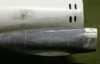 As I had decided to do a version that was
fitted with the Reaction Motors rocket-unit, I had to modify the fairing under
the rear fuselage that housed the rocket-motor. I started by superglueing the
provided metal exhaust-piece to the rear of the fairing and proceeded by glueing
two lenghts of Contrail strut-rod to each side of the fairing, providing a
foundation for building it up to a semi-round form that blended into the
exhaust-part. This was accomplished with Tamiya putty and careful sanding and I
finished the entire assembly off with several fat coates of Humbrol
Glosscote(well cured between coates) to provide a good surface for scribing
panel lines.
As I had decided to do a version that was
fitted with the Reaction Motors rocket-unit, I had to modify the fairing under
the rear fuselage that housed the rocket-motor. I started by superglueing the
provided metal exhaust-piece to the rear of the fairing and proceeded by glueing
two lenghts of Contrail strut-rod to each side of the fairing, providing a
foundation for building it up to a semi-round form that blended into the
exhaust-part. This was accomplished with Tamiya putty and careful sanding and I
finished the entire assembly off with several fat coates of Humbrol
Glosscote(well cured between coates) to provide a good surface for scribing
panel lines.
Staying on the tail end of the aircraft, I blanked off the upper two of the rocket exhausts(that should have housed the Curtiss Wright unit) with a slice of thin acetate, detailed with vent-holes as per photos( I had now, late in construction, finally recieved a copy of the Pace book: Air Force Legends: XF-91, with lots of helpful photos). I also detailed the rocket exhausts with miniscule end-rings, cut from small-diameter Contrail tubing.
I now turned my attention to the cockpit area and decided to try on the canopy. After cutting it out of the sheet(yes, I was very,very careful), to my chagrain grande, I found it to be too wide and all wrong in profile(too high and rounded, windshield too steep). Faaan i helvete!!(won´t translate that!). There´s nothing more effective, short of winter ice-baths, too cool off the enthusiasm of this modeler, than useless kit clear parts.
 Well………………(mind working, cog-wheels
turning)………. I tried the KR-kit canopy that had a better profile but was way
too big to fit. No other replacement parts available in this world, that´s for
sure! Me not yet risen to the heights of self-vacuforming either. Hmmm…….
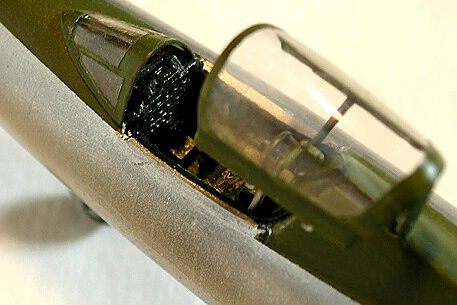
I finally decided to cut the canopy open
and display it this way. This would at least take the edge of that tubby side
profile. The windshield of the XF-91 was also V-shaped with a sharp
edge going down the middle while the
kit-part was rounded. I heated the part in hot water and gently folded it over a
knife-edge and managed to achieve some of the real-life form, but it was still
way too short and steep. I finally took the KR-kit-canopy, sawed off the
windshield ( which is far better in profile),
carefully folded it in on itself down the middle and sanded down on the sides
until it fit the fuselage contour. The end result was nowhere near perfect
though, but as close as I could do it, given the available material. I kept the
kit-bit canopy to be posed in the open position later in construction.
Well………………(mind working, cog-wheels
turning)………. I tried the KR-kit canopy that had a better profile but was way
too big to fit. No other replacement parts available in this world, that´s for
sure! Me not yet risen to the heights of self-vacuforming either. Hmmm…….
I finally decided to cut the canopy open
and display it this way. This would at least take the edge of that tubby side
profile. The windshield of the XF-91 was also V-shaped with a sharp
edge going down the middle while the
kit-part was rounded. I heated the part in hot water and gently folded it over a
knife-edge and managed to achieve some of the real-life form, but it was still
way too short and steep. I finally took the KR-kit-canopy, sawed off the
windshield ( which is far better in profile),
carefully folded it in on itself down the middle and sanded down on the sides
until it fit the fuselage contour. The end result was nowhere near perfect
though, but as close as I could do it, given the available material. I kept the
kit-bit canopy to be posed in the open position later in construction.
So I was stuck with an open cockpit (not so bad really, considering the substatial investment made by installing the Tamiya-tub) and had to do some more work in this area. The canopy mechanism of the XF-91 required opening up a narrow hatch in the fuselage-fairing behind the cockpit.The canopy swings up in a parallellogram pattern(á la F-84F), supported by two side-arms and another strut at the back. I routed this part out using an Xacto-blade cut off at the right width of the hatch. I also added cockpit-sills from scrap PE parts, lined with narrow strips of black insulation-tape, simulating the rubber canopy-seal.
|
PAINTING & FOILING |
With the main sub-assemblies more or less finished it was time for a true Rolls Royce paint-job(you know about this, don´t you? When all parts are painted before assembly. I had two friends that went to England with the perfect idea of a great business-deal, bought a vintage Bentley 1955, took it back to Sweden, put it through(what they thought) a super paint-job and put it out on the vintage-car market. Inspected by the true connaisseurs it was, of course, immediately declared worthless, not being painted with the Rolls Royce method. They had to ship it back to Britain and sell it for half the initial price( not to mention the travel costs). Even the best of ideas can boomerang right back in your face, just like some of my novelty modeling methods sometimes do!)
Allright, so my plan was to do the entire aircraft in Bare Metal Foil after having tried it out on the fin and found it looking super. After a good week of wrestling the somewhat snakey pieces of metal foil I had the entire plane covered. Looked like sh*t! I couldn´t get the overlaps between different panels right, no matter how careful I followed the instructions. So followed another good week of undressing the poor Thunderceptor and I have some inside info. for you modelers out there: some Metal Foil come off easy, some don´t! Some of it leave a lot of hard-to-get-rid-of residue-glue, some of it just peels off.
Seems to be a difference between sheets of different shades of metal. Chrome is the worst(to get off, best to get to stick). I had to wash the entire plane with white spirit in order to get it cleaned up for another try at a NMF. I actually didn´t make it all the way with the undressing and chose to leave a band of Chrome Foil around the rear fuselage that I thought I could blend in to good advantage. Foolish me!
Anyway, I now chose SNJ for the next try and made a, let´s say, acceptable job of it. It was just that the area I had left in Chrome Foil stood out like a flashlight in contrast to the rest of the airframe. I hadn´t dared spray the SNJ over the metal foil as I didn´t know if it would adhere or just run off. I finally tried spraying the area with Testors Dullcote and a couple of layers brought the sheen down to a less blinding level.
Overall, I tried to copy the different shades of metal finish that, sort of, goes round the fuselage in bands, polishing the SNJ in different degrees. The wing/tailplane center sections are also in a markedly flatter and more grey tone than the rest of the wing and these areas were left in unpolished SNJ. Oh, and the fin was left in it´s ”original” metal foil finish.
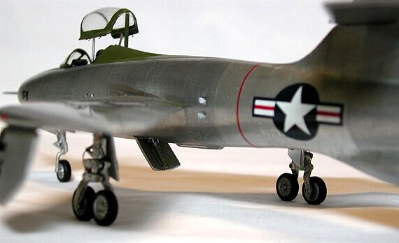
I wasn´t entirely satisfied with parts of the spinal joint so I sanded/Mr.Surfacered this again, masked for the fuselage trim and sprayed Olive Drab(for which I used Humbrol 98). This was also done on the wing walkways( All main parts still separate, remember? Nice/easy to mask/handle, the Rolls Royce folks know what they are doing!).
I also discovered, via the Pace book and correspondence on the Forum, that the wheel-wells weren´t in zinc-chromate yellow as you might have expected. They were in natural metal too and I had to repaint these, no big deal(just goes to show the importance of good ref. material).
|
CONSTRUCTION CONTINUES |
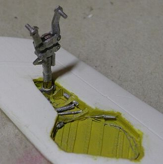 I assembled the u/c main units and added
some fine fuse wire for brake lines. The construction of the units was somewhat
confusing before I realized I had to cut off some pegs here and there to make
it fit. They looked terrific when finished. I also elongated the legs with short
pieces of brass-tubing to compensate for the deepened wheel-wells and to make a
sturdy fit into the brass-tube mounts. This construction also left me a little
room for lengthwise adjustment, in order to get the ”sit” of the aircraft
correct.
I assembled the u/c main units and added
some fine fuse wire for brake lines. The construction of the units was somewhat
confusing before I realized I had to cut off some pegs here and there to make
it fit. They looked terrific when finished. I also elongated the legs with short
pieces of brass-tubing to compensate for the deepened wheel-wells and to make a
sturdy fit into the brass-tube mounts. This construction also left me a little
room for lengthwise adjustment, in order to get the ”sit” of the aircraft
correct.
Main gear doors from the kit were used(the inner/upper doors are really small and a bugger to sand out to the proper shape) and detailed with inside skins, riveting and hinges/actuators. Nose gear was lengthened with brass-tubing(same system as the main gears) and recieved a self-produced scissor-link. Nose-gear doors were sculpted from stock styrene(kit parts too small) and outfitted with hinges, inventively cut from Evergreen I-beam.
|
DECALS |
Do you still follow my, somewhat eccentric, building plan? I was now ready for decaling of the beast and I had initially planned to do the decaling in subassemblies, just as with the painting. For alignment issues, however, I decided to put the wings onto the fuselage at this point. This was executed with no major problems. Just some careful superglue application, and the engineering of the kit worked as promised.
The kit-provided decals proved to be very thick and were printed on a continous sheet, making up for some trouble with carrier film showing on the model if not cut out very carefully. I decided to use stuff from other kits or aftermarket and all ”stars ´n bars” were taken from an Expert´s Choice sheet(kit-decal national insignia are all wrong sizes, anyway). However, I had to use the provided U.S.A.F lettering as I couldn´t find any replacement in this particular font/size. Decaling of the wing undersides was a real puzzle-affair with all those hefty gear doors. I decaled the fin separately with items taken from an Airfix F-80 kit + the kit tail numbers.
After leaving the decals to set overnight, I somehow managed to drop the fin to the floor, scratching it rather badly, and was forced to strip the foil off this part too. It was repainted with SNJ and decaled once again with lettering from another Airfix F-80 + tail numbers from various sources in the decal dungeon/kit stash. Pheeew!!
The XF-91 logos on the nose are kit decals minus the ”Republic” part, as photos reveal that 6680 omitted this part in the later stages of flight testing. These nose logos are a trifle too big and too fat, but OK then! Decals were sealed with a coat of Future.
|
FINAL STAGES |
The remaining subassemblies where now joined; tail, undercarriage, gear doors, windshield and canopy. Canopy mechanism is a mixture of Italeri swing-arms and scratchbuilt(canopy hooks came courtesy of a F-15 PE-set). Belly speed-brake was made from sheet styrene and detailed with scrap PE-stuff. Hinges were cut from Evergreen I-beam. Some paint touch-up was executed, nav.lights, fin pitot and nose probe mounted and the Thunderceptor was finally finished.

|
CONCLUSIONS |
As always with vacforms, a lot of work is involved if you want to build a reasonably detailed model.
The Maintrack kit provides a real good starting point with a correct and well detailed airframe, exceptional u/c setup and all parts needed for the various subvariants. You get an acceptable representation of the XF-91 by doing it OOB( the only exception being the not-so-good clear parts). If you want a more detailed model you´ll have to consult your kit stash/decal dungeon and do some scratchbuilding, as per the above.
On the whole, it turned out OK. Some parts can be done a lot better, particularly the NM-finish, but this is an ongoing learning experience and the next model will hopefully be one step up on the ladder.
Thank´s for looking!
|
REFERENCES |
Pace: Air Force Legends No.210, Republic XF-91 Thunderceptor.
Airpower magazine, Sept. 1986, Vol.16 No.5.
Copyright ModelingMadness.com. All rights reserved. No reproduction in part or in whole without express permission.
If you would like your product reviewed fairly and fairly quickly, please contact the editor or see other details in the Note to Contributors.