
|
KIT: |
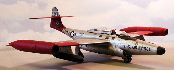
Revell 1/48 F-89D/J Scorpion |
|
KIT # |
4568 |
|
PRICE: |
$16.00 (1992) |
|
DECALS: |
Two Aircraft |
|
REVIEWER: |
Roger Jackson |
|
NOTES: |
Kit is currently out of production |
|
HISTORY |
The end of the Second World War in September of 1945 was seemingly the death knell for propeller-powered warplanes everywhere as the victorious and erstwhile Allies scrambled to embrace the emerging jet turbine technology. In the United States, wholesale cancellations of contracts for thousands of propeller aircraft for both the Army and Navy likened the resultant pandemonium among the major aircraft companies to the panic on the Titanic’s lifeboat deck.
One of the newly-created United States Air Force’s first orders of business in 1947 was to mandate an all-turbine inventory of combat aircraft as soon as practical to maintain America’s aerial supremacy. With the Japanese surprise air raid on Pearl Harbor still relatively fresh in the national psyche, special emphasis was placed on creating an impenetrable air defense network to protect the continental United States from airborne aggression.
The Air Force’s fledgling Air Defense Command was tasked with this responsibility, developing and deploying a vast, integrated system of long range radar installations throughout the country and extending north into Canada and the Alaskan Territory. The northern-most sites become known collectively as the DEW (Distant Early Warning) Line and climatic conditions in these arctic areas were among the most severe imaginable.
Providing ‘teeth’ for the ADC became problematic as the Air Force’s first-generation jet fighters lacked sufficient range, firepower, and avionics to perform adequately in the interceptor role. In many areas prop-driven holdovers from WWII were still in use, totally ill-suited for this critical mission. A dedicated all-weather fighter was clearly needed to accomplish this vital task but military funding in the post-war era had been slashed to ridiculously pitiful levels.
In 1949 the Soviet Union detonated its first atomic bomb in the hinterlands of Siberia, shocking most Western defense analysts and forcing the development of a purpose-designed all-weather interceptor from the back burner to center stage. The Russian Air Force had previously demonstrated an ambitious strategic aircraft program fully consistent with offensive operations on a global scale. The stage seemed set for a Cold War showdown.
In the spring of 1945 the United States Army Air Force had issued a requirement for a new night fighter. The specifications mandated a top speed of 550mph, a combat radius of 600 miles, and the ability to reach 35,000ft in twelve minutes. Wartime exigencies prevented most major airplane companies from seriously considering the AAF proposal but after VJ day and the resulting fiscal famine it became Katie bar the door! Six manufacturers, eager for orders—any orders, submitted designs in 1946, most of them employing the then-new turbine powerplants.
The Northrop Corporation had distinguished itself during WWII with America’s only purpose-built night fighter, the P-61 Black Widow, and its twin-jet, two-seat N-24 was one of the more promising proposals received. In June of 1946 Northrop was awarded a contract for two flyable prototypes, to be designated XP-89. The first example took to the air two years later, re-labeled the XF-89 as the new separate Air Force had ordered all “P” (for Pursuit) designations changed to “F” (for Fighter).
Like its progenitor the Black Widow, the new interceptor was painted glossy jet black and introduced several novel concepts including decelerons. Developed by Jack Northrop personally, these were simply split ailerons that permitted the control surface to perform dual duty as a speedbrake, allowing for much more rapid deceleration throughout the entire flight envelop. Double-slotted flaps were fitted to the broad-chord low aspect ratio wings to give the aircraft better than average short field performance, deemed critical in order to deploy the plane to forward areas lacking lengthy runways.
Initially the fighter was to be equipped with a retractable and fully articulated turret in the nose containing four M-24 20mm cannon and 1080 rounds of ammunition. Delays with this Rube Goldberg-esque system resulted in the XF-89 making its debut unarmed while additional difficulties forced the turret arrangement’s eventual abandonment in favor of a more traditional fixed gun configuration. Bulbous fuel tanks holding 600 gallons were installed at the wingtips in an attempt to satisfy the range stipulations in the original contract.
Though fundamentally sound, the XF-89 prototype’s shortcomings were soon apparent and included less-than-adequate thrust and acceleration, structurally deficiencies with the empennage, and center-of-gravity problems. Up-rated J-35 engines equipped with afterburners and newly-incorporated auxiliary blow-in doors for the revised intake ducts provided a substantial increase in available thrust, while a re-design of the tailplane strengthened this assembly.
 The C/G problem was resolved with a three-foot
extension inserted in the fuselage just forward of the wing. This plug added a
considerable amount of interior volume to the aircraft so the originally
envisioned armament of four 20mm guns with 270 rounds each was revised to
include two additional 20mm weapons with 1200 rounds total. The remaining
excess space was occupied by additional ‘black boxes’, seemingly
developed on a near-daily basis.
The C/G problem was resolved with a three-foot
extension inserted in the fuselage just forward of the wing. This plug added a
considerable amount of interior volume to the aircraft so the originally
envisioned armament of four 20mm guns with 270 rounds each was revised to
include two additional 20mm weapons with 1200 rounds total. The remaining
excess space was occupied by additional ‘black boxes’, seemingly
developed on a near-daily basis.
To decrease wing loading and maintain the contract-specified combat radius, new non-jettisonable tip-tanks were designed. These tanks, though smaller by half in capacity than the prototype’s, were more streamlined and actually decreased parasitic drag, contributing greatly to the aircraft’s overall performance. In a nebulous departure from the XF-89’s designated primary mission, a spurious secondary air-to-ground capability was added, with provisions for bombs and/or rockets to be carried under the wings. The gloss black paint job though visually striking was discarded as the last vestiges of the ‘night fighter’ era mutated into the more apropos all-weather concept.
The radical changes from the original prototype demanded a new designation and prior to actual production the Air Force obliged, amending the nomenclature to YF-89A. Flight test crews and ground personnel at Muroc Dry Lake (later renamed Edwards AFB) had likened the similarity of the aircraft to a scorpion, with its outstretched pincers and high curling tail. Thus the new interceptor was named the Scorpion. Following a lengthy flight test program fraught with unforeseen difficulties the Air Force placed an order for 48 aircraft in the summer of 1950.
Only eight F-89As were actually built, with the remainder of the order modified into ‘B’ models while still on the production line. Continuing difficulties with tailplane flutter and fire control system reliability were the primary reasons and most of the original F-89As were quickly relegated to training units as instructional airframes. A few became crash and rescue practice exercises with less than 200hrs on their airframes (!).
The F-89B introduced external mass balancers to the elevators and a center brace for the large canopy frame. A Lear-Siegler autopilot and upgraded avionics became a standard fit, along with an improved engine, the J-35-A-21A. Deliveries of the F-89B began in May 1951 though by 1954 most of these aircraft had been transferred to various Air National Guard units as the much-improved F-89C became available.
Improvements to the J-35 engine and internally balanced elevators were hallmarks of the F-89C, while the whimsical hard-points for air-to-ground ordnance on the earlier models were unceremoniously deleted. 164 were built with the first aircraft delivered in September of 1951. Less than six months later the entire Scorpion fleet was grounded following the catastrophic loss of six aircraft in very short order due to unknown structural failure.
The problem was diagnosed as aerodynamic flex, causing the main wing spar to fracture at the root and disintegrate during high-G maneuvers combining rapid pitch, yaw, and/or roll control inputs. All extant Scorpions received strengthened wing attachment clips and stabilizing fins to their tip-tanks then returned to duty. The F-89C’s active service was relatively brief and by December 1954 they too had been handed over to the ANG.
Meanwhile the inevitable first clash between East and West had occurred on the Korean Peninsula in June of 1950, transforming Cold War suspicions into heated confrontation. Shortly after the onset of hostilities the Soviets dropped another bomb, figuratively and literally—they tested their first thermo-nuclear device.
Apoplectically, the Truman Administration demanded assurances from the Air Force that United States airspace would remain inviolate. General Hoyt S. Vandenberg, the USAF’s Chief of Staff, attempted to calm the waters by offering public platitudes guaranteeing total sovereignty of the country’s borders. Privately, behind the closed doors of highly-classified Congressional sub-committee meetings, his testimony revealed some serious shortcomings within the ADC.
In the case of the F-89 the problem was crystallized as lack of airspeed. In preliminary intercept trials against a mock attack using the Air Force’s new B-47 jet bomber as a target, the Scorpion was found to have absolutely no chance of overtaking or even keeping up with this aircraft. The only potential for a successful engagement lay in a lead-collision course attack from the target’s 12 o’clock position, a risky proposition in its own right and certain in the fact that no follow-on pass would be possible if the pilot missed with the first fusillade.
 With proof positive that the Soviets were
developing indigenous jet-powered bombers, the engineers at Northrop embarked on
a major redesign of the Scorpion’s armament, fire control system, and
powerplants to maintain the F-89’s viability. The cannons were deleted and a
new nose was fitted. Blunter and slightly longer than the earlier snout, it
mounted a much improved search-and-track radar and an additional fuel tank
holding 262 gallons.
With proof positive that the Soviets were
developing indigenous jet-powered bombers, the engineers at Northrop embarked on
a major redesign of the Scorpion’s armament, fire control system, and
powerplants to maintain the F-89’s viability. The cannons were deleted and a
new nose was fitted. Blunter and slightly longer than the earlier snout, it
mounted a much improved search-and-track radar and an additional fuel tank
holding 262 gallons.
Spin-stabilized folding-fin aircraft rockets (FFARs) providing substantially more destructive capability were intended as the Scorpion’s new sting. They were to be housed and launched from re-designed wingtip pods which performed dual duty as fuel tanks, holding 308 gallons apiece. Fifty-two projectiles could be carried in each pod, transforming the F-89 into a most formidable platform.
Pylons plumbed for 300-gallon drop tanks and located outboard of the main landing gear were carried over from the earlier ‘B’ and ‘C’ models, while an improved J-35-A-33 engine was developed to produce more thrust and better reliability at altitude. The Air Force thought well enough of the re-design that it ordered it into production as the F-89D.
Construction was temporarily suspended when wing problems surfaced with the F-89C and it was not until January of 1954 that the F-89D became operational. Thirty fighter interceptor squadrons would eventually receive the ‘D’ model with 682 aircraft ultimately built. During the latter stage of this production run experiments elsewhere with radar-guided air-to-air missiles began to yield results, with the Hughes GAR-1 Falcon demonstrating particular promise.
Northrop, with an eye on growth potential for the Scorpion, wisely incorporated provisions for an additional pair of pylons under each wing of the last 350 F-89Ds on the assembly line to facilitate carriage of the new Falcon missile if and when the Air Force so decreed. The Scorpion would indeed carry the Falcon but it would be the F-89H which would debut its deployment.
For this incarnation the Scorpion was fitted with new wingtip pods, each capable of carrying three GAR-1s (or its newly developed infrared-guided counterpart, the GAR-2) mounted on retractable racks fitted into individual bays, plus 21 FFARs arranged annularly in triplets of seven. Standard tactical doctrine became a 50/50 combination of both types of Falcon missiles to be ripple-fired in mixed pairs. As with the ‘D’, fuel was carried in the rear of these pods. An improved fire control system was fitted to accommodate the Falcon missile while the remaining features and specifications for the most part were unchanged from the F-89D.
Production of the F-89H amounted to 156 aircraft and their service tours in regular Air Force units were comparatively short due to developmental delays. It entered the inventory in March of 1956 just as Convair’s supersonic F-102 was certified for service. The ‘H’ models were transferred to the ANG in short order though by 1959 these too were retired as F-86Ds and F-102s became available to Guard units.
The final chapter of the Scorpion’s odyssey became the F-89J. This was an effort to give the Scorpion a punch equivalent to the new F-101B and F-106A “Century Series” interceptors while minimizing R & D costs. The final 350 ‘D’ models (those with the additional under-wing hardpoints) were returned to the factory and remanufactured to the new F-89J specifications which included provisions to carry and launch the unguided (!) nuclear-tipped Douglas MB-1 Ding Dong rocket (“Like tryin’ to swat a fly with a sledgehammer…”) plus a mixed quartet of GAR-1 and –2 Falcons with conventional warheads.
All weapons were to be carried externally on underwing pylons while the wingtip rocket pod/fuel tank combos were supplanted by a slender fuel-only 600-gallon tip-tank. The fire control system was replaced by the MJ-12, featuring a new ballistic computer calibrated to the MB-1’s programmed trajectories. Corrosion and moisture control difficulties with the Falcon missile forced their deletion from the F-89J early on, leaving the 1.6 kiloton-yield Ding Dongs (redesignated the AIR-2A Genie) as its sole armament.
The F-89J became operational in January of 1957, issued to a total of eleven regular Air Force squadrons. Following their transfer to a like number of ANG units in the early ‘60s, they were ignominiously relegated to the role of backstopping ADC’s new fleet of Voodoos and Delta Darts. Though less glamorous than its contemporary stablemates, the SabreDog and the Starfire, the Scorpion out-lasted them both with the last F-89Js retired in the autumn of 1969.
|
THE KIT |
Revell’s F-89D/J Scorpion kit is comprised of 105 parts molded in silver-gray styrene, five transparent pieces, and decals to complete one F-89D or one F-89J. A foldout instruction sheet offers a brief summary of the Scorpion’s history and specifications, a generic painting guide, and a recommended assembly procedure.
The surface detail consists of raised panel lines with recessed vents, scoops, and movable control surface reveals. The fuselage has a separate keel piece which may prove troublesome unless carefully pre-fitted and adjusted prior to assembly. Separate intake ducts are provided, along with a simulated engine compressor fan assembly which obviates the need for installing a baffle to prevent see-through.
The large wings feature flashed-over holes for the different external stores combinations, forcing a choice between the versions before assembling them. The wingtip rocket pods for the ‘D’ variant depict the rockets slightly proud of the fronts. More correctly, they should be fully recessed into individual launch tubes.
The cockpit offers a 21-piece layout including a pair of four-part seats, specific and different instrument panels for each of the two variants, and two mediocre figures. Details here are in raised relief and though somewhat heavy, perform the role adequately after a proper paint and weathering job. Clear parts are furnished for the radio compass housing and the RSO’s blast shield (F-89J only).
 The landing gear
is robustly sturdy and realistically appointed with individual retraction jacks
for each strut and separately attached doors. Full wheelwells are cast into the
lower wings though most of this area will be concealed after assembly. The
tires are treaded and the wheels accurately reflect the prototype, though only
the solid hub nose wheels, used mainly on the ‘J’ but only seldom seen on the
‘D’, are included.
The landing gear
is robustly sturdy and realistically appointed with individual retraction jacks
for each strut and separately attached doors. Full wheelwells are cast into the
lower wings though most of this area will be concealed after assembly. The
tires are treaded and the wheels accurately reflect the prototype, though only
the solid hub nose wheels, used mainly on the ‘J’ but only seldom seen on the
‘D’, are included.
The installation of the tailplane and fincap may prove problematic when filling and sanding the joints. Solid gluing is necessary to prevent damaging this fragile assembly when handling the model. The joint can be strengthened by engineering and installing a reinforcement pin through the fuselage portion of the fin and the fincap’s large mounting tab.
Under wing stores consist of a pair of two-piece 300-gallon drop tanks with integrally molded pylons for the ‘D’ model, plus four Falcon missiles and two Ding Dongs for the ‘J’. Proper pylons for all six weapons are provided but lackluster moldings handicap the ordnance. Replacements from the Hasegawa ‘C’ set and the Monogram F-101B are recommended for those modelers constructing an F-89J.
The clear parts are exceptional and fit well though the separate canopy and frame require sanding and re-polishing for a properly blended fit. The radio compass antenna is molded to the underside of the canopy while a wiper arm and blade is depicted on the windscreen’s center pane. A clear landing light lens mounts on the fuselage forward of the gear well while a prop is included for those neglectful modelers who forget to add ballast to the nose.
The decals feature 52-2155, an F-89D-50-NO assigned to the 61st FIS at Ernest Harmon AB, Newfoundland, circa 1955-57. Markings for F-89J 52-1949, which in its previous life was an F-89D-45-NO, represent the 124th FIS, Iowa ANG, based at the Sioux City Municipal Airport during the twilight era of the Scorpion’s career. (Your editor thinks the 124th was the last unit to fly the Scorpion as most of the various museum F-89s he has seen were in those markings.)
The sheet is dramatically striking but many of the multicolored items on the review copy were severely off-register. Service stenciling is minimal, consisting primarily of emergency egress information, numerous ‘NO STEP’ warnings, and the unique Y-shaped foot and hand guide for boarding the aircraft. Though the adhesive on the backing paper seems heavy, the carrier film is thin and responds well to setting solutions.
Missing from the kit is the lightning arrestor at the front of the radome, the white position lights located on the aft fuselage, a raised outlet duct on the starboard side of the canopy rib, and the emergency barrier engagement hooks below the nose and belly (required for some F-89Ds and all F-89Js). Late ‘J’ aircraft also mounted red anti-collision beacons ventrally between the engines and dorsally at the rear of the canopy frame. These overlooked details are easily added with a little research and common hobby materials.
|
CONSTRUCTION |
Calculating the amount of ballast necessary to keep the Scorpion properly perched on its tricycle landing gear was my first concern, so after mocking up the major airframe components with masking tape I plotted that value by placing the model on a wooden dowel. As it teetered on the C/G point I placed automotive wheel weights on the nose until sufficient heft caused the mock-up to pitch forward definitively.
 Nearly four
ounces were needed and I increased this figure by a few grams to provide added
insurance as any further details installed to the rear of the C/G would
exacerbate an already critical situation. After un-taping the model I detailed
the numerous airframe parts individually, starting with the fuselage.
Nearly four
ounces were needed and I increased this figure by a few grams to provide added
insurance as any further details installed to the rear of the C/G would
exacerbate an already critical situation. After un-taping the model I detailed
the numerous airframe parts individually, starting with the fuselage.
Here, I opened up all the scoops and ducts, adding some illusion of depth to these items. Those forward of the cockpit I completely walled off and compartmentalized from the inside to prevent any glue from seeping or dribbling out when I anchored the wheel weight ballasts there. The cooling gills aft of the wing roots seemed a little murky so I cut rectangles into the fuselage and installed some photo-etched grilles instead, baffling them from the inside to avoid see-through as these louvers are symmetrically located.
 After
shoe-horning all the lead counterweights into the nose, the fuselage was
assembled and the seams filed and sanded flush. I discovered the missing
lightning arrestor on the tip of the radome through research and added that
little detail, using a short length of #25 hypodermic needle and a piece of
.013” guitar string. The radome was glued on then I moved to the cockpit.
After
shoe-horning all the lead counterweights into the nose, the fuselage was
assembled and the seams filed and sanded flush. I discovered the missing
lightning arrestor on the tip of the radome through research and added that
little detail, using a short length of #25 hypodermic needle and a piece of
.013” guitar string. The radome was glued on then I moved to the cockpit.
Revell’s representation here is adequate though the molded-on lap and shoulder restraints were removed from the seats and replaced with paper belts and a pair of Model Technologies photo-etched buckle sets. I installed a pair of throttles on the pilot’s left console and a few doo-dads to both seats using brass wire, sheet styrene, and nylon bristles from a hair brush after first flaring the ends with low heat to form small knobs.
The clear radio compass housing (part# 103) was replaced by a new piece made from a transparent orange-colored shaft left over from by dart-throwing days at the NCO club. After turning it down to the proper diameter with my Dremel tool I shaped the top into a dome, sanded it smooth, then polished it with a buffing wheel and jeweler’s rouge.
The interior
parts were sprayed with 36270 Neutral Gray while the panels and consoles were
brush-painted with flat black. I highlighted the raised details there by
dry-brushing, first with 36440 Gull Gray followed by a lighter touch of flat
white. After painting the headrests flat red I sealed everything with a heavy
blast of Testor’s Dullcote. Powdered graphite was dusted into the seat buckets
and on the floorboards to give them some artificial depth and shadow. After a
light airbrushing with Dullcote I installed the cockpit in the assembled
fuselage.
The simulated compressor fan assembly was sprayed with Testor’s aluminum Metalizer and buffed lightly with a scrap of cotton T-shirt. Fit of this piece into the fuselage was a bit fiddly but careful positioning prior to actual gluing accomplished the mission. The fuselage keel (part# 18) proved even more troublesome. After shaving two of the fuselage mounting tabs and shimming two others with small drops of dried CA, I got it flush enough for 9-level work and glued it on.
The intake duct parts had a small amount of casting flash at the lips so I chamfered and radiused the openings to uniform size. Some tooling marks and large mold release plugs on the insides were sanded away and once glued to the engine nacelles look convincing unless viewed at danger close range and illuminated with a judge’s ubiquitously de rigueur ‘weenie light’.
The tailpipes were assembled and installed after first spraying the insides with flat black and dusting them with powdered graphite to provide a little ‘soot’. Departing from the instruction sheet, I elected to glue the deflectors on first as these parts required some adjustment for a proper symmetrical fit.
 With the basic
fuselage completed, I compared it to my reference photos and discovered the
missing marker lights located axially in three positions forward of the fin.
White sprue was used to fashion the teardrop blisters which were installed
peg-style into pre-drilled holes and held with CA. Likewise, I used white and
yellow sprue to replicate the dual position lights at the tail.
With the basic
fuselage completed, I compared it to my reference photos and discovered the
missing marker lights located axially in three positions forward of the fin.
White sprue was used to fashion the teardrop blisters which were installed
peg-style into pre-drilled holes and held with CA. Likewise, I used white and
yellow sprue to replicate the dual position lights at the tail.
New pitot tubes were fashioned from #20 hypo needles to be installed prior to painting. Several attempts to form the necessary 90-degree bends resulted in the tubes kinking due to the brittleness of the material. Borrowing from a gunsmith friend, I took the temper out by heating the needles over a candle flame. After easily shaping the parts to the proper configuration I re-tempered the tubes by heating once again and immediately immersing them in cold water. A light polishing with crocus cloth restored their luster and color.
The crater-sized mounting depressions for the original plastic pitot tubes were filled with sprue and sanded flush. New flush mounting sockets were made from partially crushed aluminum tubing and installed in the centers of each plug to provide a snug friction fit for them. The refrigeration outlet duct on the right side of the aft fuselage seemed less than convincing so I re-built it, using a piece of 3/32” aluminum tubing installed obliquely and sanded flush with the surface.
The avionics bay cooling scoops were assembled and cleaned up prior to gluing them on. I drilled them out for more depth and affixed them with Testor’s liquid cement. Consistent with my own modeling convention, I tacked the windscreen on with liquid cement then used CA to blend it to the fuselage. While filing and sanding this joint smooth, I removed the windshield wiper which would subsequently be scratch-built from metal parts.
 I began rescribing the fuselage at this point since it was still easy enough to handle.
Here I found a major error with the original raised surface detail as Revell had
incorrectly depicted the prominent set of multiple blow-in panels on the
intakes. Instead of the prototype’s four uniformly-sized, equidistantly-spaced
doors, they are shown as decreasing in height from top to bottom. A logical
conjecture would be that the design engineer and the mold cutter interpreted
these details by viewing a side elevation only, failing to account for
this feature’s three-dimensional aspect when rotating the fuselage through a
90-degree arc to planform.
I began rescribing the fuselage at this point since it was still easy enough to handle.
Here I found a major error with the original raised surface detail as Revell had
incorrectly depicted the prominent set of multiple blow-in panels on the
intakes. Instead of the prototype’s four uniformly-sized, equidistantly-spaced
doors, they are shown as decreasing in height from top to bottom. A logical
conjecture would be that the design engineer and the mold cutter interpreted
these details by viewing a side elevation only, failing to account for
this feature’s three-dimensional aspect when rotating the fuselage through a
90-degree arc to planform.
If not corrected the ‘NO STEP’ decals which will ultimately be applied on each door will appear awkward and spurious. Strips of masking tape were used to lay out a grid pattern which I used as a guide to create a properly configured quartet of doors on each intake duct. This was perhaps the most challenging part of the operation as the trial-and-error process resulted in a fair share of minor missteps.
Next I re-scribed the tailplane and fincap then assembled them as a unit. Test-fitting this to the fin revealed looser-than-Tamiya tolerances between the mounting tab and the slot. With the propensity for handling damage high due to the delicate area to be glued and the awkwardly immense size of the model, I decided to reinforce this joint with a taper pin. I drilled a 3/16” hole through both sides of the fin at the tab’s intended location then tacked the empennage on with a single drop of Crazy Glue.
I carefully plotted the centers of the holes relative to the mounting tab and marked their location on both sides with a center punch. After popping the tailplane assembly off I drilled a hole through the mounting tab at my datum marks, purposely undersizing it to provide a snug fit when the pin was inserted. I turned a short piece of sprue down to 3/16” and installed it through the holes with the empennage in place. After sanding the ends of the pin flush with the fin, CA was used to fill some small gaps there and to create a slightly radiused fillet between the bottom of the tailplane and the fin.
 The fuel
tank/rocket pod combos were assembled after I first removed the molded-on
position lights and replaced them with pre-shaped teardrop blisters of red and
green Lexan. For total fidelity I should’ve removed the visible rocket warheads
and drilled out the launch tubes. Hmmm…dozens of aggravating holes requiring
precision alignment and painstaking uniformity or an afternoon at the firing
range with my CAR-15? Duh…no contest!
The fuel
tank/rocket pod combos were assembled after I first removed the molded-on
position lights and replaced them with pre-shaped teardrop blisters of red and
green Lexan. For total fidelity I should’ve removed the visible rocket warheads
and drilled out the launch tubes. Hmmm…dozens of aggravating holes requiring
precision alignment and painstaking uniformity or an afternoon at the firing
range with my CAR-15? Duh…no contest!
I sectioned the drop tanks from their integral pylons to permit installation after painting, thus eliminating the need to mask the tanks. Also, I wanted to install the pylons on the wings prior to painting to minimize handling dings in the paint and just as well, as the pylon-to-wing interface did not appear to be optimum without some filling and sanding. Fuel dump vents were added to the trailing edge of each pylon, using short pieces of #20 hypo needle.
Slight warpage with the wing halves required a few warm water dips and some judicious hand flexing to correct. Once they were mated and glued I attached the large main gear doors in the proper closed position. Disregarding the instructions again, I added the rocket pods to the wingtips. The fit here was notably poor, requiring repeated filling and sanding. After an acceptable fit was achieved I rescribed both sub-assemblies then discovered something truly incredible…the wings are HEAVY!
The pair of them easily out-weighed a completed P-38 in my display case by several grams. Compounding this, the mounting tabs were slightly undersized to the fuselage slots. Total reliance on adhesive for a structure this massive is not my style so I used 3/32” square brass channel to create two partial wing spars, installed in the fuselage forward and aft of the slots at the wingroots. The front one became another Don Quixote-esque dilemma as the spar ran right through the cockpit. Thankfully I was able to conceal it by situating it just forward of the RSO’s instrument panel.
Once the spars were solidly attached to the fuselage I bent them slightly up to achieve and maintain the near-imperceptible dihedral. Holes were cut into the wings at the butt end of the roots so I could slide them over the brass spars. After a couple of test-fits and some minor adjustments to the spar angles, I removed the wings.
The underwing pylons were sanded and rescribed, along with the assembled drop tanks. Brass pins and sheet aluminum sway braces were used to mount the tanks to the pylons, with friction itself as the ‘adhesive’. The wings were again temporarily attached to the fuselage so I could tack the pylons on in the proper perpendicular (from front elevation) position. Once they had been correctly aligned I glued them solidly with CA, then filed and sanded the joints smooth. The wings were likewise affixed and I had a ‘flyable airframe’.
 A substantial
amount of ‘thrust’ was necessary to power the model through a demanding series
of test hops around my studio and I began to fear for the long-term durability
of the landing gear. During one of these trial sorties I discovered the missing
outlet duct on the rear fuselage when comparing the model to my reference
photos. A small piece of sheet aluminum was quickly tin-smithed into the proper
shape, to be attached with a small bead of CA. Several +/- 5G maneuvers
validated the model’s basic construction and the structural integrity of my
modifications so I moved to the final phases of assembly.
A substantial
amount of ‘thrust’ was necessary to power the model through a demanding series
of test hops around my studio and I began to fear for the long-term durability
of the landing gear. During one of these trial sorties I discovered the missing
outlet duct on the rear fuselage when comparing the model to my reference
photos. A small piece of sheet aluminum was quickly tin-smithed into the proper
shape, to be attached with a small bead of CA. Several +/- 5G maneuvers
validated the model’s basic construction and the structural integrity of my
modifications so I moved to the final phases of assembly.
With the moment of truth at hand I cleaned up and detailed the landing gear struts. Small diameter wire replaced the molded hydraulic lines while cast brass eye bolts replicated the tie-down rings. No front or rear bulkheads for the nose well are provided so sheet styrene was used as a stand-in, installed in conjunction with the door assemblies. After attaching the struts I used shorts pieces of .010” guitar string to fashion a set of actuators for the nose doors and moved to the wheels.
Strictly picking nits here, there are three distinct styles of nose wheel for the Scorpion. The solid cast type included in the kit seems to have been used most often with the F-89J, and only seldom with the ‘D’. Most F-89Ds, according to published photos, used the six-spoke unit as issued with the earlier ‘A’, ‘B’, and ‘C’ versions. A third option is a finned ‘turbine’ design which apparently was fitted to only a handful of ‘D’ models. A good example of this wheel is shown in the photo of “Swing Shift Skipper” on page 24 of Squadron-Signal’s F-89 In Action.
It looks suspiciously like the main wheel hub of Lockheed’s F-80 Shooting Star with a tire diameter close to the Scorpion’s nose unit and that’s exactly what I used, pirating them from the Monogram kit. After assembling the F-89’s main gear wheels I cut new tread into all four tires, then painted and installed them. The remaining doors were attached with liquid cement then, with palpable trepidation, I checked to see if I had unerringly cheated gravity by placing the model on its landing gear.
My C/G and ballast calculations rivaled Rob Leatham’s combat pistol accuracy, with the nose wheels solidly planted on the workbench. Attempts to rock the model back resulted in a resounding ‘thud’ as the Scorpion pitched forward into the required tricycle stance. After filling the hole for the now-unneeded tail prop I toasted my success with a double Jack Daniels ‘over’ and finished the remaining construction.
 The inside of
the canopy frame was painted flat black and after shaving off the paint from the
mating edge, I glued the canopy to it using Testor’s liquid cement. After a
week of drying time I ran a bead of Crazy Glue over the seam then filed and
sanded it smooth. A buffing wheel and jeweler’s rouge were used to re-polish
the canopy and windscreen (note to blasphemers and heretics: I believe Future
belongs on a FLOOR).
The inside of
the canopy frame was painted flat black and after shaving off the paint from the
mating edge, I glued the canopy to it using Testor’s liquid cement. After a
week of drying time I ran a bead of Crazy Glue over the seam then filed and
sanded it smooth. A buffing wheel and jeweler’s rouge were used to re-polish
the canopy and windscreen (note to blasphemers and heretics: I believe Future
belongs on a FLOOR).
The windshield wiper was replicated using a modified straight pin for the articulated arm and a short piece of .010” guitar string for the blade. A new mount and bearing made from a length of #20 hypo needle was inserted into a hole drilled in the front of the fairing. After a quick test-fit to insure the blade rested correctly on the center pane, I removed the wiper and sent the Scorpion to the paint shop.
|
PAINT & DECALS |
The choice of color schemes was never an issue as I’d already decided to paint the model in arctic colors. After spraying the common areas of the radome, anti-glare panel, and fincap I masked off the wingtips and tail then shot several heavy coats of Modelmaster flat Insignia Red. Normally I use a white or light gray undercoat for this color but in this instance I thought the added spectral brilliance a light-toned primer provides would be inappropriate. After removing the masks I then set the model aside on its wheels to dry………for four years!
If nothing else, the lengthy hiatus provided ample opportunity for the wings and/or the landing gear to sag or skew. They did not.
Returning to finish the model, I masked the previously painted areas, stuffed Kleenex into the cockpit, and wrapped the tires with 3M ‘Post-It’ notes. Testor’s Chrome Silver was used overall on the remaining portions, with a specially-modified cardboard box drafted for duty as a painting cradle. The masks were immediately removed afterward and the silver was allowed to dry for a month while I located and procured decals.
Initially, I wanted to duplicate the markings furnished in Revell’s geriatric ‘box-scale’ (approximately 1/80th) Scorpion originally issued in 1957. This model featured the arctic red ID areas, basic generic insignia, and a large, menacing scorpion intended purely as a fin decoration. However, I could not locate a proper scorpion decal of sufficient size.
 Switching to
‘Plan B’, I decided that this would be a tribute aircraft to commemorate my
year-long ‘unaccompanied tour’ assignment with the Alaskan Air Command at a
remote, snow-bound mountaintop radar installation (my libido was NOT so
amused!). The resultant scheme does not represent any specific aircraft, only
the prototypical appearance of one (note: F-89s were long gone by this time—our
interceptors during my tour were all F-4Ds, “summer help” ANG F-102s, and
periodically, Canadian Forces F-101s on detached duty from Comox).
Switching to
‘Plan B’, I decided that this would be a tribute aircraft to commemorate my
year-long ‘unaccompanied tour’ assignment with the Alaskan Air Command at a
remote, snow-bound mountaintop radar installation (my libido was NOT so
amused!). The resultant scheme does not represent any specific aircraft, only
the prototypical appearance of one (note: F-89s were long gone by this time—our
interceptors during my tour were all F-4Ds, “summer help” ANG F-102s, and
periodically, Canadian Forces F-101s on detached duty from Comox).
The kit’s decal sheet provided serials and buzz numbers while SuperScale’s 48-382 was tapped for national insignias and service logos. Neither of these sheets has much in the way of service stenciling so I raided the spares box for most of it. The data block was pieced together from Monogram’s F-100 decal and reflects the correct block and serial numbers to correspond with the model’s tail markings. The large ‘AAC’ unit crest was taken from MicroScale’s 72-187 which I’d been hoarding for decades, anticipating just such a mission.
With the model suitably marked, I sealed the decals with Testor’s Dullcote then highlighted the panel lines with dark gray Liquitex watercolor. A final flat coat waterproofed the weathering then I added the final details. White decal stripe was applied to the windscreen and canopy framing to simulate the window seals while the fuel caps on the wings got red decal dots.
Underneath, I substituted an MV lens for the kit’s landing light, held in place with a dollop of white glue. The drop tanks were sprayed flat black and press-fitted onto their pylons then I installed the stainless steel pitot tubes. After dropping the windshield wiper into position I used diluted white glue applied with a 000-brush to hold it in position.
I wanted the canopy removable for maintenance or inspection so I installed a nylon pin on the underside at the rear. A corresponding hole was drilled with a #77 drill bit on the spine’s canopy track to keep the canopy centered on the fuselage. The slides at the front were slightly modified for a tighter fit to the rails and the canopy was positioned and fitted sans adhesive.
|
CONCLUSIONS |
Revell’s F-89D/J Scorpion is a good kit, though not without vices. Fit problems may confound novice modelers while structural difficulties will prove challenging even for veteran enthusiasts. Revell really deserves to be commended for daring to kit one of the more esoteric subjects from America’s early jet age and assembly anxieties aside, the only valid criticisms I can offer concern the ordnance for the F-89J variant, the figures, and the off-register decals.
Though appealing enough, the printing errors rendered the markings for the most part unusable and the brevity of the stenciling furnished compounds the problems. Aftermarket items are available from both SuperScale and Bare Metal so this shortcoming is not insurmountable. However, neither of these companies provide much in the way of service stenciling on their available offerings either so a well-equipped spares box will be a big help.
Moreover, the external stores are terrible, poorly shaped and with ill-fitting parts. From two meters distance under dim lighting they might pass muster, but as the range decreases and illumination improves their mediocrity becomes painfully apparent. Better missiles can be found in Monogram’s F-101 and F-106, though the ‘Six’ kit contains only one Ding Dong. An alternative source for replacement Falcons is the Hasegawa ‘C’ weapons set.
Likewise, the figures are Cro-Magnon icons time-warped straight from the 1950s. It’s difficult to understand how they made it into such an otherwise fine kit, though most modelers find the idea of gluing figures into a detailed cockpit a bit passé anyway. If figures are necessary or desired, better options are available from a number of sources, including Monogram’s vast array of ‘50s-era and ‘Century Series’ jets.
The one real regret I have is that a scaled-up version of the famous ‘Revelling’ stand like that issued in the stone-age ‘box-scale’ Scorpion was not included—it would make ‘flying’ this ponderously huge behemoth so much easier!

|
REFERENCES |
F-89 Scorpion; In Detail & Scale – Bert Kinzey; Airlife Publishing LTD
F-89 Scorpion In Action – Larry Davis & Dave Menard; Squadron-Signal Publishing
U.S. Fighters Of The Fifties – Nico Sgarlato & Franco Ragni; Squadron-Signal Publishing
The History Of The US Air Force – Bill Yenne; Exeter Books
Air Force – Martin Caidin; Bramhall House
Personal Observations, Pima Air & Space Museum; Tucson, Arizona
Ó March 2002 by Roger M. Jackson
First Time North American Rights To Scott Van Aken and ‘Modeling Madness’
If you would like your product reviewed fairly and quickly by a site that has well over 100,000 visitors a month, please contact me or see other details in the Note to Contributors.