| KIT: | Lincoln 1/65 Sycamore |
| KIT #: | ? |
| PRICE: | $? |
| DECALS: | ? |
| REVIEWER: | Carmel J. Attard |
| NOTES: | Also released by Lincoln |
| HISTORY |
The Bristol 171 was the first designed and built helicopter in Britain after the WWII. The prototype, VL958 first flew on the 24thof July 1947, and it was intended for military and possibly civilian purposes. Initially the choice of engine was made difficult in view of the lack of a suitable unit at the time. The first two prototypes were powered by a Pratt and Whitney Wasp Junior but eventually the Leonidas engine started to be produced and was used on subsequent helicopters employed on ground trials programme.
On the 3rd of September of 1949 the Leonidas
powered Mk2 VW905 made its first trials and on a second attempt the rotors
disintegrated. There was delay in fitting new blades before further flying was
undertaken. A production version, Mk3 had then evolved and this had provision
for five persons with a modified cabin area besides other engineering changes.
The ministry of 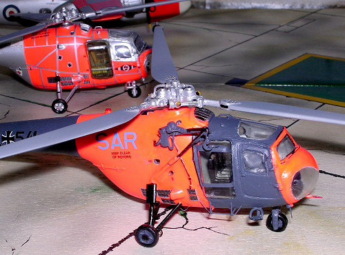 supply gained the first 15 produced and G-ALSX became the
company demonstrator while G-ALSR went to BEA for a period of time before being
acquired by the Royal Aircraft Establishment. Others were used for operational
and evaluation trials as casualty evacuation HC10, ASW HR12, Army and Air
Observation Post HC11, and air-sea rescue and Coastal Command HC12. Three
Sycamores found their way to the Woomera rocket range, Australia.
supply gained the first 15 produced and G-ALSX became the
company demonstrator while G-ALSR went to BEA for a period of time before being
acquired by the Royal Aircraft Establishment. Others were used for operational
and evaluation trials as casualty evacuation HC10, ASW HR12, Army and Air
Observation Post HC11, and air-sea rescue and Coastal Command HC12. Three
Sycamores found their way to the Woomera rocket range, Australia.
Sycamores were attached to a number of overseas RAF Stations for air-sea rescue duties as well as local liaison flights in Cyprus, Aden and Kenya. These have proved their utility in rescue missions both over the sea and in mountains, forests and deserts where aircraft have been forced down. In Malaya the Sycamore proved its main test and usefulness where it provided the ideal rescue means as opposed to the conventional difficult rescue operation by land. At one time No 194 Sq employed 23 Sycamores in Malaya, followed by 110 Sq which received six, this later emerged with 155 Squadron. Sycamore operations in tropical jungle were far from smooth and several came to grief due to lack of adequate landing clearance or structural failures and other incidents through losing tail or rotor blades. The Sycamore provided useful life and achieved service in the Far East until partly replaced by Whirlwind helicopters in September 1963 when Sycamores continued to operate alongside the Whirlwinds.
 Besides the RAF, Sycamores also went to other services.
Fifty were purchased by the Germans and used by Bundesmarine for SAR and
communication tasks; others were used by the Whermacht as liaison aircraft.
Other Sycamores went to civil use in Germany. Three went to Belgium and 13 MK 50
to the Royal Australian Navy to operate from ships and shore bases. Sycamores
built up valuable rotary wing experience. The RAAF operated two Sycamores (A91-1
and A91-2) and used almost exclusively for the Woomera Rocket Range in South
Australia.
Besides the RAF, Sycamores also went to other services.
Fifty were purchased by the Germans and used by Bundesmarine for SAR and
communication tasks; others were used by the Whermacht as liaison aircraft.
Other Sycamores went to civil use in Germany. Three went to Belgium and 13 MK 50
to the Royal Australian Navy to operate from ships and shore bases. Sycamores
built up valuable rotary wing experience. The RAAF operated two Sycamores (A91-1
and A91-2) and used almost exclusively for the Woomera Rocket Range in South
Australia.
Sycamores became well known to the public due to assistance they provided in flood rescue and other civil emergency work. In these areas they pioneered many of the techniques and capabilities that are nowadays taken for granted. During such operations Sycamores have demonstrated a high degree of reliability and many owe their lives upon a survival mission by a Sycamore.
| THE KIT |
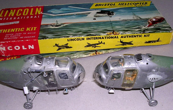
Long time ago I have acquired two scale models of the Bristol Sycamore helicopter model made by Lincoln International of Hong Kong. This goes back to the late 60s which I bought from a Sliema model shop for the value of 1s 6d. Same shop now sells sub aqua equipment in these changing times. However this did not happen to be the only Sycamore kit that exists since during 1988 Maintrack Models released a ‘resin and white metal kit’ of the Bristol Sycamore HC14. Since then there has been another kit released by Glencoe This I have discovered is an identical kit to the ones in my possession previously made by Lincoln Int. From the dimensions that I read off the booklet on Type 171 Mk IV Sycamore Helicopter Technical Notes SEB 183 dated 1958 issued by Sales Engineering of Bristol Aircraft Limited and measurements I took of the actual model at various places I have found that it was at a scale of 1/64.7 or 1/65. to the nearest. So it is clear that it is not a 1/72-scale model as some may advertise it as being so..
 The large rotor diameter is 48’ 6.7” and
that of the kit is 9”. This works a ratio of 64.74: 1: the tail rotor
calculation comes out as 64.73:1, and the distance between the propellers centre
lines is 64.72:1. So the kit is over scale by 10%. The kit comes in a cardboard
box measuring 9”x3.3”x 0.75”and the box art depicts a dramatic scene of a
Sycamore hovering over a downed aircrew about to be recovered from a survival
dinky. To its right is a sinking swept wing aircraft, possibly a Scimitar and
two aircraft carriers appear in the vicinity A comprehensive instruction sheet,
8.5”x 3” comes with the kit which also contains a detailed line drawing of the
main rotor mechanism intended to assist with correct assembly of the somewhat
detailed and accurate rotor parts.
The large rotor diameter is 48’ 6.7” and
that of the kit is 9”. This works a ratio of 64.74: 1: the tail rotor
calculation comes out as 64.73:1, and the distance between the propellers centre
lines is 64.72:1. So the kit is over scale by 10%. The kit comes in a cardboard
box measuring 9”x3.3”x 0.75”and the box art depicts a dramatic scene of a
Sycamore hovering over a downed aircrew about to be recovered from a survival
dinky. To its right is a sinking swept wing aircraft, possibly a Scimitar and
two aircraft carriers appear in the vicinity A comprehensive instruction sheet,
8.5”x 3” comes with the kit which also contains a detailed line drawing of the
main rotor mechanism intended to assist with correct assembly of the somewhat
detailed and accurate rotor parts.
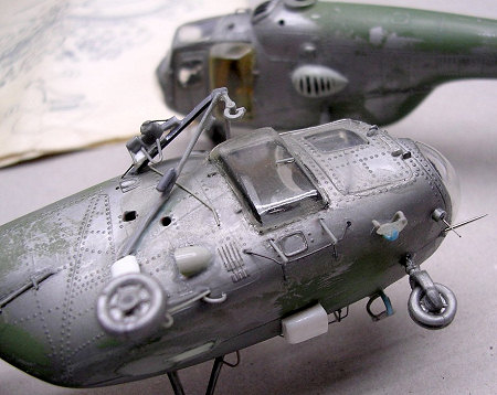
The kit comes in silver plastic sprues that contain 17 parts that form the main rotor; 8 parts for the interior cabin compartment and seating, 8 parts for the undercarriage detail, 7 parts for the fuselage and tail rotor detail and 7 clear plastic parts, which brings a total of 47 parts besides the 2 part stand. There are no numbers pressed on the sprues but the illustrated exploded view is easy enough to follow. I hardly ever use a stand so one has to keep in mind to blank off the slot cut in the fuselage floor. The smaller plastic parts were contained in a small single plastic bag. Flash was present with almost all parts and a simple task will clear all this using a smooth file. One job that certainly needed doing was the removal of excessive and oversize rivet detail though this appears to be in the right place. The rear door outline is recessed; this has in fact proved helpful in my case because it marked the area that I had to remove to form the required opening . I preferred to make versions that had clear blisters installed in place of doors. The front doors are moulded separately and I preferred to assemble these in the closed position.
 The easy to follow instruction lists 29
stages of assembly. Strangely enough the instrument panel is not drawn to the
correct perspective as the rest of the drawing and this may mislead one to
assemble it in the horizontal position when in fact this should be vertical. The
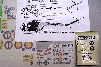
decals that come with the kit are useless as even the roundels are incorrectly
registered and instead of an authentic serial number there is HC671 that did not
seem to make any sense. Thanks to Maintrack Models who provided substitute
decals. Even so the instruction sheet certainly helped to assemble the rotor
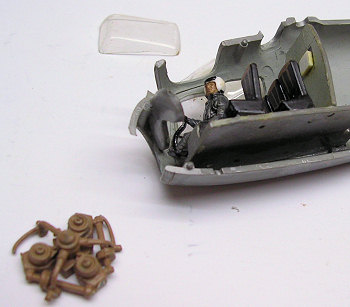
unit to form an admirable detailed rotor head as shown in picture. This
incorporated the rotor hub, control spider assembly, control axle, ball joint,
blade link, centrifugal droop stop, flap hinge pin, hinge assembly, blade lever,
rotor hub etc as shown in picture.
The easy to follow instruction lists 29
stages of assembly. Strangely enough the instrument panel is not drawn to the
correct perspective as the rest of the drawing and this may mislead one to
assemble it in the horizontal position when in fact this should be vertical. The
decals that come with the kit are useless as even the roundels are incorrectly
registered and instead of an authentic serial number there is HC671 that did not
seem to make any sense. Thanks to Maintrack Models who provided substitute
decals. Even so the instruction sheet certainly helped to assemble the rotor
unit to form an admirable detailed rotor head as shown in picture. This
incorporated the rotor hub, control spider assembly, control axle, ball joint,
blade link, centrifugal droop stop, flap hinge pin, hinge assembly, blade lever,
rotor hub etc as shown in picture.
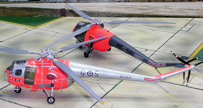
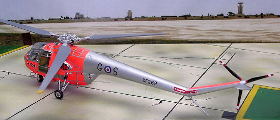
As indicated earlier, I made two different versions out of my two scale models, A German navy Mk52 WE541 and an HC14 of the RAF Central Flying School XF269. I have selected these two versions as these carry among the most colourful colour schemes that one could find on helicopters both of which have Day-Glo orange areas.
| CONSTRUCTION |
Making these versions entailed several
alterations apart from detailing the models. The German Mk 52 also required
fitting a winch and hoist being a search and rescue version. This hoist is
fitted to the starboard fuselage side, which is powered by a main gearbox
mounted hydraulic pump. This type carried blisters in place of the standard
doors. Some RAF rescue versions the starboard aperture is covered by a canvas
screen with quick opening action. An intercom connection is provided to enable
a crew 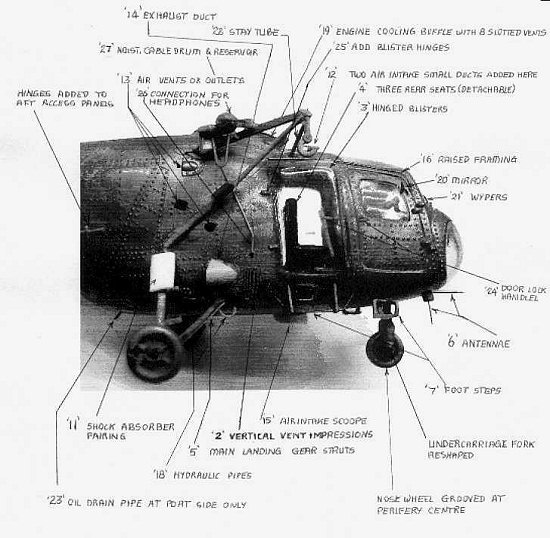 member who descends on the winch to communicate with the pilot. This
fitting was also represented on the kit.
member who descends on the winch to communicate with the pilot. This
fitting was also represented on the kit.
The RAF dual instruction version has done away with the hoist assembly but it was also equipped with side blisters in place of the aft doors. The instructor’s seat is installed on the port side and duplicate instruments are fitted if required on a panel immediately in front of the seat. A cyclic pitch stick with rudder pedals is fitted for the instructor.
Improving the Sycamore scale models necessitated the following alterations and additional details. Reference is also made to the labelled diagram with respect to the sequence number:-
1) Removing excessive rivet detail on both fuselage halves.
2) The vertical ventilation ports on the lower fuselage sides were extended upwards using a sharp pointed scraper.
3)
The two front doors were glued in place and the
rear ones were cut to form an opening 12mm x19mm. This aperture will later take
the moulded acetate blisters. This feature appears to be standard on the greater
part of Sycamores. This has originated on rescue models that
necessitated the installation to carry
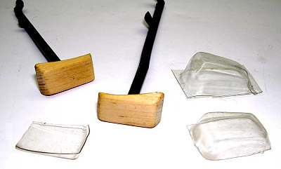
two stretchers. By adding the blisters one gained extra cabin width to take the
stretchers crosswise. Each blister is slightly inclined towards the rear at the
upper end. This also meant that two different wooden blister male moulds had to
be prepared, one for each side (see picture). These moulds
 produced
the blisters from clear acetate. Each one produced was trimmed with a small pair
of scissors until the correct shape was size obtains the best fit.
produced
the blisters from clear acetate. Each one produced was trimmed with a small pair
of scissors until the correct shape was size obtains the best fit.
4) For all type of roles with the exception of passenger transport role the aircraft was normally equipped with three canvas seats in the rear cabin and one seat besides the pilot. This seat could be turned rearwards if required. In the passenger transport role a fully upholstered bench type seat is fitted. All seats were quickly detachable. I have used the ones provided with the kit on the SAR German version and added only one rear seat to the RAF trainer version but detailed the rear bulkhead in each case. At this stage the side and front windscreens were fixed in place using Kristal Kleer not to cloud the clear panes if glue is used. No reference is made to add weight to the nose area. T play safe I added flat strips of lead under the forward section of the cabin floor. The fuselage halves could now be assembled to form one piece and the open stand slot at the bottom was blanked off using putty followed by sanding down.
5) Main landing gear struts were reduced in thickness and fitted in place at the side of the fuselage. While the RAF version had a straight tube shock absorber with exposed corrugated rubber boot to the upper end, the German version appeared to have a flat cover fairing fitted The nose wheel fork leg was reshaped straight with a smooth file. The front wheel also had a central groove added using a narrow file edge at the circumference.
 6)
Two antennae were added to the front of the forward
fuselage as shown in picture reference. Two inverted “U” shaped antennae were
added to the exterior of the roof and a rectangular antenna added under the
boom. In the RAF version a whip aerial was added instead.
6)
Two antennae were added to the front of the forward
fuselage as shown in picture reference. Two inverted “U” shaped antennae were
added to the exterior of the roof and a rectangular antenna added under the
boom. In the RAF version a whip aerial was added instead.
7) Foot steps were built from stretch sprue and added to the cabin close to the doors on each side.
8) Tail skid was reduced in thickness and fixed in place.
9) Tail rotors were carefully reduced in thickness using a smooth file.
10) A tiny red warning light was added to the tail boom.
11) The moulded acetate blisters were added at this stage.
12) Two tiny air ducts facing towards the rear were shaped from a piece of plastic and fitted to the roof area.
13) Three outlets were drilled at different positions on starboard side and one on upper port side.
14) An exhaust outlet on the lower starboard side had a faired cover made from a fuel tank piece and fitted in place.
 15)
A large air intake scoop of rectangular section was
made from plastic card and added under the fuselage and to the left of the
centreline.
15)
A large air intake scoop of rectangular section was
made from plastic card and added under the fuselage and to the left of the
centreline.
16) Raised framing was added to the roof perimeter and to the upper edge of the rear excess doors.
17) A tear drop shaped fairing was made from a fuel tank side and slotted vents added to the surface of it. This standard item was missing from the kit and added to both versions on the port side of the fuselage.
18) Hydraulic pipes added to front undercarriage strut. These were shaped from stretch sprue.
19) Part No 19 which is the engine cooling baffle and is positioned on top of the fuselage had 8 vents carefully opened with sharp exacto knife and shaped with a file.
20) A mirror made from piece of shaped plastic card and steel pin was fitted to front starboard door on the German Sycamore only.
21) A pair of wipers was added to the front screens.
22) .A tiny vent was drilled half way down on the boom.
23) Oil drain pipe made from a steel pin was stuck to the aft port lower fuselage.
24) Tiny locking handles made from a narrow strip of plastic were added to all four doors
25) Add two hinges to each blister. These are fitted to the rear of the blister.
26) Connection cable for head phones was made from a narrow stretch of sprue and cut to size and fixed in place.
27) Hoist cable drum, winch motor, reservoir complete with bob weight and hook to form the hoist apparatus were made from scrap plastic and fitted in position.
28)
A stay tube was finally fitted to the roof and
reinforced the hoist from the rear.
| COLORS & MARKINGS |
No specific color or painting information supplied. Ed.
| CONCLUSIONS |
The Sycamores have seen active service in the RAF and Luftwaffe Air Force besides other Forces. It definitely filled up a space in rotor aviation before the Whirlwind helicopters started to emerge and eventually replace the RAF ones. It certainly made an interesting addition to my rotorcraft section of my model collection.
If you would like your product reviewed fairly and quickly by a site that has over 350,000 visitors a month, please contact me or see other details in the Note to Contributors.