| KIT #: | KH80115 |
| PRICE: | $85.00 SRP |
| DECALS: | Four options |
| REVIEWER: | Tom Cleaver |
| NOTES: |
| HISTORY |
The F-101 Voodoo
was the end product of an Air Force design concept first broached in 1947, for a
long-range jet fighter capable of providing escort to SAC B-36 and B-50 bombers.
The initial response to the design requirements came from North American
with their F-93, a beefed-up Sabre; McDonnell with their F-88, the first to be
given the name “Voodoo”; and the Lockheed F-90.
All were underpowered, and in the meantime the B-47 came on the scene,
followed by the B-52, obviating the need for escort fighters.
The Air Force continued working with McDonnell to create a long range
“penetration” fighter. With J-57s
finally providing the necessary power, the F-101 first appeared in 1953.
It was capable of Mach 1.5, with a useful range.
SAC had lost interest, and the Tactical Air Command had the airplane
foisted on it, with modification to turn it into a long range nuclear strike
fighter.
| THE KIT |
Over the years,
there have been a few kits of the McDonnell F-101A/C Voodoo, starting with - if
I recall correctly - a box-scale kit from Revell some 55+ years ago.
Hasegawa released a 1/72 RF-101C in the 1960s which became the subject of
one of the first resin conversion sets in the 1980s, released with a set of
decals 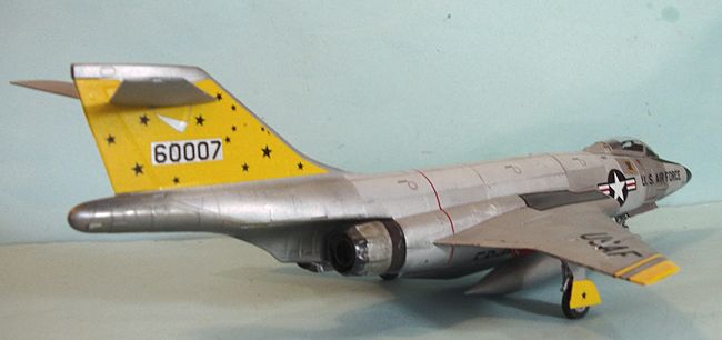 by
Super-Scale for the fighter.
Following the release of the 1/48 F-101B by Monogram, Bill Koster released
vacuform conversions to do both the F-101A/C and the RF-101A/C.
Moving on, C&H Aero released a resin conversion for the Monogram kit to
create both the F-101A/C and the recon birds some ten years ago.
This kit from Kitty Hawk is the first designed-for-the-purpose F-101A/C
kit in 1/48 and has been the subject of much speculation.
by
Super-Scale for the fighter.
Following the release of the 1/48 F-101B by Monogram, Bill Koster released
vacuform conversions to do both the F-101A/C and the RF-101A/C.
Moving on, C&H Aero released a resin conversion for the Monogram kit to
create both the F-101A/C and the recon birds some ten years ago.
This kit from Kitty Hawk is the first designed-for-the-purpose F-101A/C
kit in 1/48 and has been the subject of much speculation.
In the box, as is the case with all Kitty Hawk kits, it looks pretty good. Crisp moldings, a minimum of flash, lightly-engraved surface detail, a good decal sheet - this one presenting F-101A and F-101C aircraft from each of the four squadrons of the 81st Tactical Fighter Wing, the only Air Force unit to operate the fighter-bomber Voodoo. It is pretty certain from the contents of the kit and the breakdown of the design that an RF-101G/H and perhaps the RF-101C will be released down the line.
| CONSTRUCTION |
For starters, one
has to realize that Kitty Hawk is the only model company that designs its kits
to fit a standard-size box, which is backwards from every other company who
order boxes to fit their kits, and leads to some very strange kit design
decisions. (Editor's note: I have purchased
several Kitty Hawk kits and this statement is not totally accurate as I've found
some boxes to to thinner [F-94 and SeaSprite] and some to be smaller in overall
dimensions [Mirage F.1].) Most particularly in this case, it leads to the
long Voodoo fuselage being divided in thirds, rather than produced in two halves
like Monogram did. Even more
strangely, the forward and aft thirds are divided vertically, while the center
is divided horizontally.
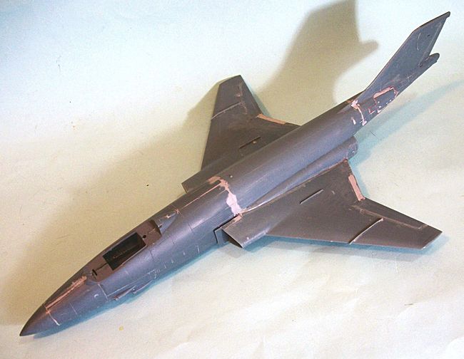 As one proceeds
with the assembly, the old Kitty Hawk problem encountered in all their other
kits raises its head. NOTHING
FITS!!!!! Thus, I am going to
outline to you what I think is the way to go about building this kit, rather
than the way I built it, since that was a process of discovering that I had
wandered into the plastic kit division of the Wong Fook Hing Book Store.
As one proceeds
with the assembly, the old Kitty Hawk problem encountered in all their other
kits raises its head. NOTHING
FITS!!!!! Thus, I am going to
outline to you what I think is the way to go about building this kit, rather
than the way I built it, since that was a process of discovering that I had
wandered into the plastic kit division of the Wong Fook Hing Book Store.
For starters,
consider this a Classic Airframes kit with better molding but otherwise just the
same. Cut off all the locating
pins, since they mis-locate what you’re trying to fit.
Do not, however, cut off the pins on the lower forward fuselage, since
they are of some important help in trying to get that lined up so you aren’t
spending for-bloody-ever trying to get rid of that seam.
Since the dive
brakes are short-shot, and (along with everything else!) don’t really fit, I
suggest you close them. Most of the
photos of F-101s I found have them closed.
Do this before you assemble the rear fuselage halves.
Fill all the sink holes, sand the brake smooth so it is smooth to the
fuselage, then rescribe the outline.
(One good thing to make note of here before proceeding further is that
you do not have to get the surface so smooth to accept a NMF finish - the F-101
only ever served painted in Coroguard, which weathered quickly in service over
in England and Europe.)
Assemble the upper
rear fuselage halves, and then attach the lower hot section to that.
Do not attach that lower part to the lower center fuselage as the
instructions say.
Moving on to the
wings, the flaps can be assembled down, but there’s not much holding them there.
While they present a blob of bright color - being red inside - most
photos of Voodoos show them raised, and it does let the speedy-looking lines of
the airplane come through. If you
should choose to do this, glue the flaps into position in the lower wing BEFORE
any further assembly, so you can work the fit from inside and outside and get
right (I definitely learned this the hard way.
Once you have made your decision on the flaps, assemble the inner
bulkhead to the lower wing half and then assemble the two wing halves.
If you followed my advice and trimmed off the locating pins, you should
be able to get this fitted nice and tight without any putty needed anywhere.
It’s now time to
consider the center section of the fuselage.
Do not assemble the inner engine and then attach it inside as the
instructions say. Cut off the
locating pins on the inner engine parts once assembled and put them aside.
You’re going to be much happier assembling each engine completely and
then sliding it into position.
Also, sand down the intake inserts so they will be flush with the rest of the
part when attached. Get them about
half as thick as they are.
 Once you have
glued the upper and lower halves of the central fuselage together, attach the
rear fuselage. Be very careful in
fighting these two sub-assemblies together, to maintain proper alignment and
insure that the vertical fin is indeed vertical, and that you do not have a
“banana” going with the fuselage.
Once you have
glued the upper and lower halves of the central fuselage together, attach the
rear fuselage. Be very careful in
fighting these two sub-assemblies together, to maintain proper alignment and
insure that the vertical fin is indeed vertical, and that you do not have a
“banana” going with the fuselage.
And now we come to
the joys of the forward fuselage.
Once you have painted and assembled and decaled the cockpit tub, set it aside.
Now proceed to assemble the three parts of each fuselage half separately,
so you can work their joints from inside and out; if you do that, you will get
good fit and not be stuck sanding seams and rescribing.
Personally, I think having the refueling probe out destroys the look of
the airplane; you may decide differently.
I glued each of the doors of the probe compartment to their respective
fuselage halves at this point, since I could get them nice and smooth working
both sides of the joint.
After you have
assembled the nosewheel well, DO NOT ATTACH IT TO THE COCKPIT TUB.
If you follow the instructions, neither assembly will align with its
proper opening in the fuselage.
Sand down the top of the wheel well to reduce the thickness by about half.
Do the same thing to the cockpit tub floor.
Then glue the
wheel well in position and let it set up, being sure the vertical alignment is
really vertical. Then slide the
cockpit into position. With the
“wiggle room” created by getting the cockpit floor and wheel well roof thinner,
you should be able to squeeze the cockpit tub into proper position.
Once you have it in position, then glue it with CA glue and zap it, and
hold it while it sets up to be sure it stays in position (that’s because it
doesn’t really want to do that, due to molding flaws).
You won’t need a
lot of nose weight here to guarantee nose sitting.
I put in one medium-sized “cannonball” fishweight and all was well.
Put that in ahead of the wheel well.
Now carefully align that lower fuselage together, and take the time to
get it really right. Then glue the
lower seam together. If you did it
right, and use hot glue, you won’t have much of a centerline seam (you might
even not have one. Now squeeze the
upper fuselage together around that @#$%%$#$#@!!
Canopy tub, get it aligned, and glue it.
You will want to use several large rubber bands to hold all this
together. Let it set up completely
before further handling.
You now get to
discover that the radome is round in section, while the forward forward fuselage
is slightly oval. Enough to make
things not fit. I glued the radome
on, then sanded it to fit the fuselage.
It really should be round, but there’s more fuselage than there is radome,
and this way you don’t have to
 rescribe a
lot of surface detail from having added putty.
Not to mention, no one will notice the cross section of the radome.
rescribe a
lot of surface detail from having added putty.
Not to mention, no one will notice the cross section of the radome.
Once all this is
done, carefully fit the forward fuselage to the rest of the fuselage.
You’ll be doing some industrial-strength pushing and shoving here, but be
sure that the alignment is such that the vertical line of the forward fuselage
really is vertical when you get it in position, and also check that “banana”
problem. Run glue around the joint,
lots of it. Then
use a wide rubber band, “spear” it on the nose and have it wrap around
the tail cone. Be certain you
haven’t got a “banana” going, and let it set up thoroughly before further
handling.
If you have done
all this right, you won’t be using much putty, but most likely you will be
puttying the centerlines of the forward and aft sections, and the joints
bringing the three sections together.
With luck, there won’t be much.
Again, you don’t have to worry about a fuselage surface for a NMF paint
job.
When the fuselage
is set up, it’s time for the wings.
Once I had them in position and ran glue into the joints, I then wrapped rubber
bands around the forward sections of the intakes, and one larger one wrapped
around the wingtips, to keep the wings tight against the fuselage while the
joint set up. Again, be sure you
have proper alignment before leaving it alone to set up.
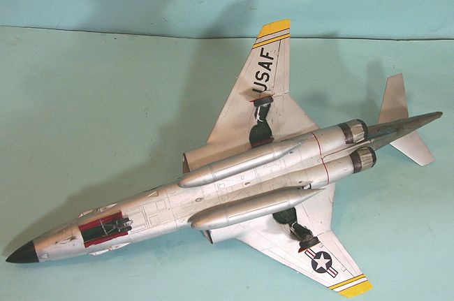
And then there are
the engines. Again, NOTHING FITS.
The various panels that fit over the burner cans have gaps, no matter how
you play with them to get them right.
I ended up using more filler here than I used on the entire rest of the
project, and then rescribed things.
I glued the inner part to the burner can and wrapped each with a rubber band to
get a tight fit. The exterior of
the burner cans was painted with Tamiya “Bronze,” “Titanium” and “Gun Metal.”
You’re now headed
for the finish line, assembly-wise and with luck, the atmosphere over the
workbench is only a light shade of violet, rather than the deep purple with
lightning bolts and thunder that I experienced.
I left off the gear and the horizontal stabilizers till after the model was painted and decaled.
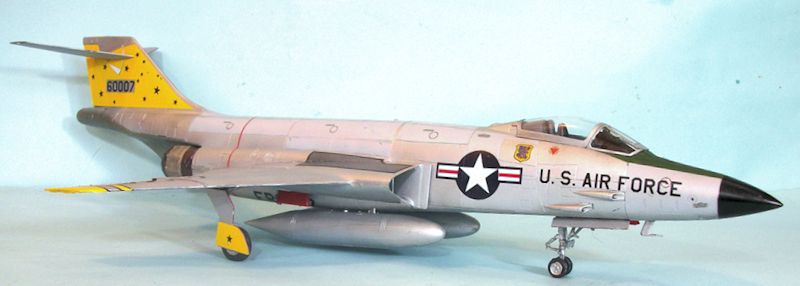
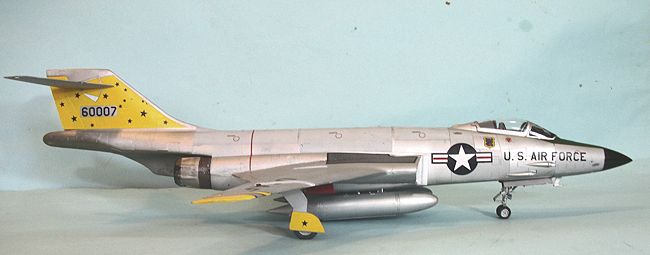
| COLORS & MARKINGS |
At the point of
painting, my model showed the physical effects of having discovered all those
neat little tricks described above “the hard way.”
I wanted to hide the thing under a paint scheme that would distract the
viewer. Fortunately, I had a photo
of the very airplane I was going to do, taken in 1965-66, after 5-6 years of
operation in European weather. The
Coroguard was “ratty.” And it was
multi-hued.
I mixed some
Tamiya “Gloss White” with “Flat Aluminum,” and painted the various panel areas
on the fuselage. I then masked
those, and gave the model an overall coat of Tamiya “Flat Aluminum” from a fresh
 bottle (nice
and smooth). I then made a thinned
mix of the “grey aluminum” and “blotched” the upper surfaces of the flat
aluminum areas.
bottle (nice
and smooth). I then made a thinned
mix of the “grey aluminum” and “blotched” the upper surfaces of the flat
aluminum areas.
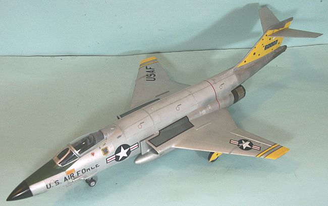
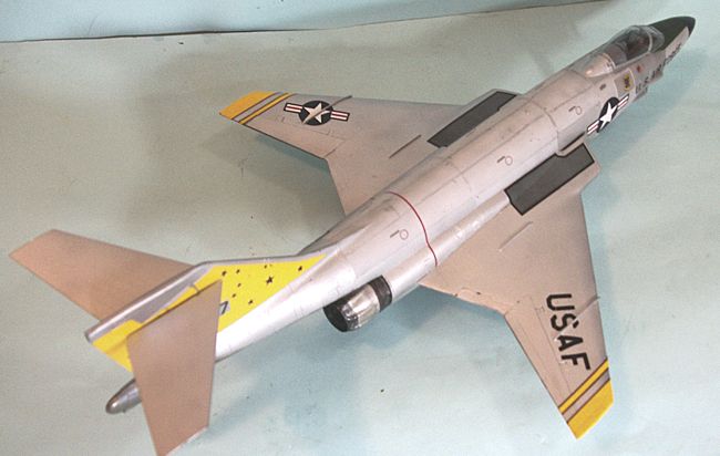
I then masked off
and painted the “exhaust” area with Tamiya “Titanium” and left it glossy.
I gave the rest of the model a coat of Model Master Sealer to keep the
surface nice and smooth for decals, without getting it shiny.
The decals go on
easily. Be sure to use lots of
water on the surface area you intend to place them, because they will grab onto
the first dry surface they find and stay there.
I only needed a very thin application of Micro-Sol to get the decals to
snuggle down. They have a flat(tish)
finish that worked perfectly with what I had created, so there was no need for
further varnishing.
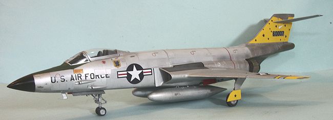
| FINAL CONSTRUCTION |
Then I found out
that the mounting pins for the main gear are too big for the holes, which are
not deep enough to seat the gear fully, and if you do that, the gear will splay
so that you have “duck feet” with the main wheels.
I cut off the pins, mounted the main gear legs with CA glue and braced
them with the rest of the gear in the well.
The gear doors managed to go on without problems.
 I slid the engine
exhausts into position and used CA glue to mount them.
I then attached the horizontal stabilizers.
I slid the engine
exhausts into position and used CA glue to mount them.
I then attached the horizontal stabilizers.
I assembled the
canopy closed because it looks better that way and there is not that much to be
seen inside. You may want to
display yours open if you get the True Details resin Voodoo ejection seats,
which will really improve the look in there.
I attempted to
attach the little vanes that go to the sides of the nose, but they both broke
when cutting them off the sprue.
| CONCLUSIONS |
At least this one
didn’t end up where the last two attempted Kitty Hawk projects did.
It’s now out in a glass case at Planes of Fame, where no one can see all
the trouble, and it looks like an F-101 to any observer.
June 2014
Thanks to Glen Coleman at Kitty Hawk for the review kit.
If you would like your product reviewed fairly and fairly quickly, please contact the editor or see other details in the Note to Contributors.