| KIT #: | 2611 |
| PRICE: | Long out of production |
| DECALS: | One option |
| REVIEWER: | Ingemar Caisander |
| NOTES: |
- Building the
"Screaming
Chicken"
in 1/8th
scale
| HISTORY |
The Pontiac Firebird first came around in 1967 and was available in five main variants: the base Firebird, the Firebird Sprint, the Firebird 326, the Firebird HO (High Output), and the beastly Firebird 400 (with a 325hp 400cui V8).
 These cars
marked the first generation of the Firebird and production continued through
1969, at which year the Trans Am was introduced (at first as a performance
option for the Firebird 400).
These cars
marked the first generation of the Firebird and production continued through
1969, at which year the Trans Am was introduced (at first as a performance
option for the Firebird 400).
In 1970 the second generation Firebird was born, sporting a complete redesign that turned it more into a "muscle car". Production of the second generation Firebird continued into 1981, with major facelifts and engine changes in 1974, 1977, and 1979.
The 1979 Trans Am could be ordered either with an Oldsmobile 185hp 403cui L80 V8 mated to a three-step Turbo Hydramatic 350 automatic transmission, or a Pontiac 220hp 400cui L78 V8 with a 4-speed manual transmission.
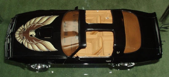
A very popular option was the T-Top: a hatch roof with two big, removable glass panels. Many Trans Ams were also ordered with the WS6 special performance package, including amongst other things a tuned suspension and four-wheel disc brakes (which was somewhat oddly indicated by stenciling on the door handles!).
| THE KIT |
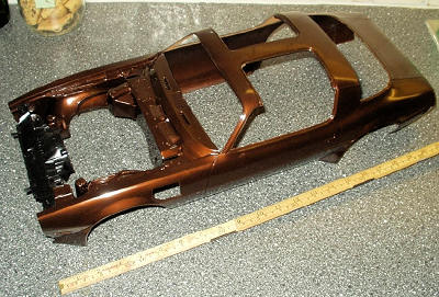
When opening the large box you are faced with a
one-piece upper body moulded in a dark brown metallic plastic, a one-piece black
lower chassis and a multitude of smaller sprues with various parts in black and
t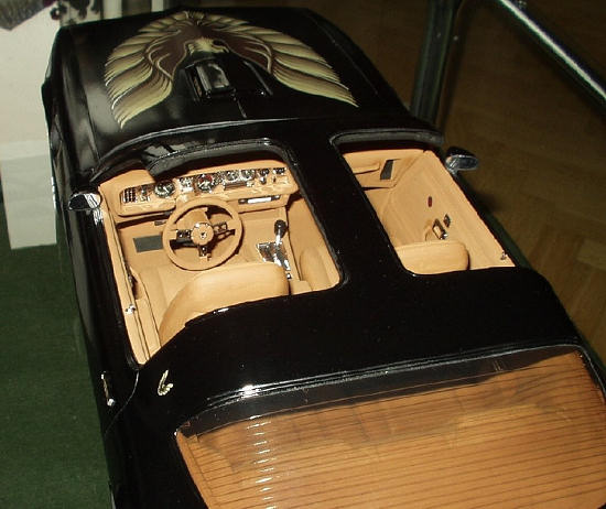 an. A bunch
of clear and chromed parts are also included.
an. A bunch
of clear and chromed parts are also included.
The large clear plastic parts, including the windshield, rear window and T-tops, are packed separately in their own plastic bags to avoid scratching.
The brown metallic plastic do not react very well to ordinary plastic cement either, making it a bit difficult to work with. Hence, during construction, I used super glue (cyanoacrylate) and two-part epoxy to join most of the parts.
A big decal sheet is also provided, this includes the instrument dials, all external Trans Am lettering as well as the beautiful golden hood bird.
| CONSTRUCTION |
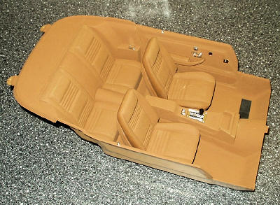
Construction began with the interior. Fit here was quite ok; some sanding and dry fitting was required to get the parts to line up properly, but nothing that required any major applications of putty.
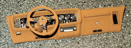
I added a very thin clear plastic sheet (coated with gloss floor wax) on the backside, and then glued the instrument decals (complete with backing paper) onto this clear sheet. When totally dry the entire backside of the instrument panel was painted flat black to prevent any unwanted color irregularities – this was necessary since the instrument decals were slightly smaller in diameter than their respective openings in the panel.
The completed panel was then attached to the dash with white glue.
The steering wheel consists of three parts with the spokes being chromed; in the center of the hub I added a Firebird decal, sealing it with a coat of gloss clear varnish.
 The
interior was painted and slightly weathered before adding all the chromed
details, such as ashtrays, door handles, gear selector etc.
The
interior was painted and slightly weathered before adding all the chromed
details, such as ashtrays, door handles, gear selector etc.
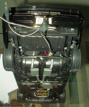
Construction was rapid as the entire bottom plate is a single black plastic part with various details added to it. This black plastic seemed to react better to ordinary glue than the brown metallic plastic did, so I used Testors liquid glue throughout construction of the chassis.
After the rear axle and differential housing were attached to the rear leaf springs, I put the whole chassis assembly to the side to let it cure completely.
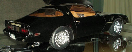
Actually, in reality, these "snowflake" wheels are gold painted and then the outside portion of the rim is machined away, exposing the aluminum underneath. I really liked the all-chrome look of the wheels, though, so I left them as they were.
The inside part of the wheels were painted silver to imitate the rotors of the disc brakes – note that the model is equipped with the WS6 package and so has disc brakes all around.
After gluing the rim halves together, trapping the rubber tire in between, the entire wheel assemblies where attached to the respective stub axles on the chassis.
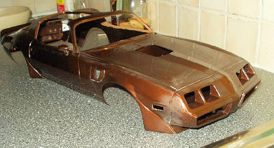
As also mentioned before, the bodywork plastic is quite hard and brittle. As a result, while trying to bend the warped large hood into a more correct shape, it cracked! This happened despite holding it in almost boiling water for a long time before any attempt was made to bend it. Fortunately the crack could relatively easily be made invisible by adding a touch of super glue to it and then sanding the surface smooth.
Each pair of red and yellow LEDs were carefully sanded flat on opposite sides and then super glued together, forming a sort of dual mount. The two center legs (LED 1 anode and LED 2 cathode, respectively) were bent and soldered together.
In addition to this, I also constructed small reflector boxes, made from 1mm thick Evergreen plastic sheet. These reflector boxes serves a dual purpose: they will prevent any light from the side position LEDs to "leak" (which could be visible through gaps and such), as well as further helping to illuminate the entire "glass" of the side position lights evenly.
| ADDING LIGHTS |
 A LED doesn’t
really emit any heat at all and it has a life span of several thousand hours
which mean it will practically last forever if not abused.
A LED doesn’t
really emit any heat at all and it has a life span of several thousand hours
which mean it will practically last forever if not abused.
The position lights on the sides each consist of dual 5mm red at the rear and dual 5mm yellow at the front. Each dual LED is rated at 4V (2V per individual LED) and consists of two LEDs connected in series, each pair being fed with 10mA through an in-series resistor of 100ohms.
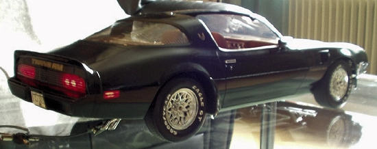
The taillights are eight 5mm red LEDs, each rated at 2V and connected two and two in series, each pair fed with 20mA through an in-series resistor of 50ohms (actually two 100ohms resistors in parallel).
 As
I wanted the lighting system to be capable of running on a wide variety of
external power supplies and at the same time protecting the LEDs, a simple
electric control system based on the familiar 7805 voltage regulator was added.
The general circuit consists of an integrated diode bridge connected to the
LM7805, with a 220uF capacitor placed in parallel between the incoming connector
of the voltage regulator and ground.
As
I wanted the lighting system to be capable of running on a wide variety of
external power supplies and at the same time protecting the LEDs, a simple
electric control system based on the familiar 7805 voltage regulator was added.
The general circuit consists of an integrated diode bridge connected to the
LM7805, with a 220uF capacitor placed in parallel between the incoming connector
of the voltage regulator and ground.
The integrated diode bridge will turn incoming AC into pulsated DC, which is then ripple-reduced or "smoothened" by the 220uF capacitor. If the circuit is connected to a DC power source the diode bridge won’t do anything (except "stealing" about 1.4V).
The voltage is then regulated down to about five volts by the LM7805 integrated voltage regulator and fed to the LEDs via the in-series resistors. As the LEDs only require about 2V each and we have 5V available from the 7805 voltage regulator, the in-series resistors will help limit the current flow in the circuit and hence provide the LEDs with the correct operation voltage.
Uhu, right.
So what does this mean?
Well, the four main headlights are each fed with 20mA, the four position lights 10mA each and finally each pair of taillights 20mA (times fours as the eight LEDs are connected two and two in series). This gives a total consumption of about 200mA or 0.2Amps (not including the power consumption of the 7805 voltage regulator itself, but as it is quite low (a couple of mAs) it can relatively safely be ignored).
So, how much is the excess power supply voltage then?
Well, if connected to a power source of 9V (like an ordinary flashlight battery), the excess drop voltage over the 7805 will be 9V minus 5V (the regulated voltage of the 7805) minus 1.4V (total voltage drop over the diode bridge), which equals 2.6V. The excess power will then be approximately 2.6V times 200mA, which equals just over 0.5Watt.
Of course, using a power source with this kind of relatively high voltage should be avoided, but just to be on the safe side the 7805 was mounted onto an aluminum heat sink (taken from the CPU of an old discarded computer).
| COLORS & MARKINGS |
As the entire kit is pretty logically divided into three main sub-assemblies: interior, lower chassis, and body, this was also the order in which I painted the model.
The interior was painted Humbrol 62 Leather and when
dry a light drybrushing of Humbrol 63 Sand was added to bring out details and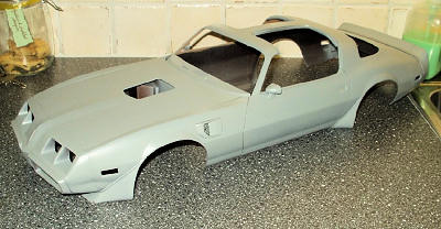 surface texture, especially on the hobnail cloth of the seats.
All chromed interior details
received a thin coat of Johnson Plastic Floor Wax (pretty much the same thing as
Future Floor Wax which might be more common for you guys in the
The exhaust system with mufflers was painted in Humbrol 56 Aluminum while the opened-up centers of the chromed exhaust tips were painted black.
Then it was finally time to bring out the black paint!
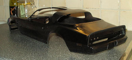 The entire
body was sprayed black in two consecutive sessions, the first coat being flat
black and the second coat a very thin layer of gloss black. This was done in
order to give the paint a more coarse and "alive" look, almost like metallic but
still a solid black. When completed, the painted body was set aside to let the
paint cure completely for a few days.
The entire
body was sprayed black in two consecutive sessions, the first coat being flat
black and the second coat a very thin layer of gloss black. This was done in
order to give the paint a more coarse and "alive" look, almost like metallic but
still a solid black. When completed, the painted body was set aside to let the
paint cure completely for a few days.
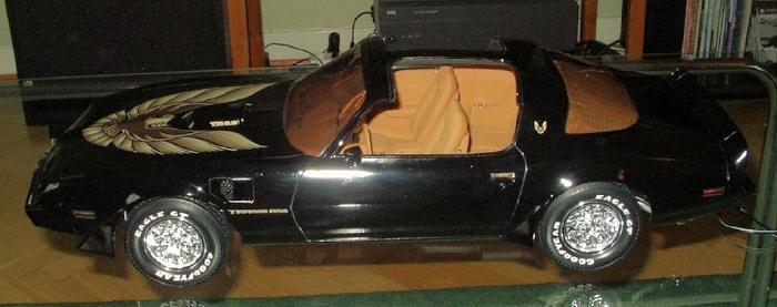
Applying the lettering on the hood "shaker" presented no problems, but when I started to add decals to the body I ran into some difficulties. The decals tended to "silver" badly, especially the "Trans Am" lettering on the front side fenders. I suppose this is mainly due to the fact that the decals are now pretty old (20+ years), hence quite inflexible and prone to develop small air bubbles underneath if not applied to an absolutely smooth surface. I therefore added an extra coat of clear gloss varnish on the hood and rear spoiler before any attempt was made to apply the big decals that were to go there. This seemed to solve the problem as the decals then went on nicely.
The damaged "Trans Am" lettering on the front fenders was repaired by carefully painting over the "silvered" areas with black paint, using the tip of a slightly bent needle.
| CONSTRUCTION CONTINUES |
 Final
assembly began with mounting the front and rear windshields to the body,
then the interior
"tub"
was glued into place. I used two-part epoxy for this, as the body plastic
didn’t like plastic cement, and I didn’t dare using super glue for fear of
fogging up the windshield.
Final
assembly began with mounting the front and rear windshields to the body,
then the interior
"tub"
was glued into place. I used two-part epoxy for this, as the body plastic
didn’t like plastic cement, and I didn’t dare using super glue for fear of
fogging up the windshield.
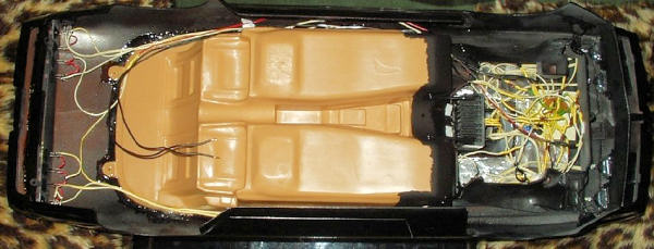
Then all
the electrics were installed – headlights, side position lights with reflector
boxes, and the eight rear red LEDs. The latter were simply inserted into the
previously drilled 5mm holes in the internal rear plate and fixed with two-part
epoxy.
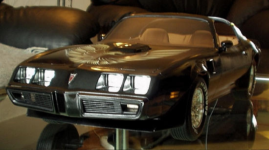
Finally the entire upper body was mated with the lower chassis, secured with the three supplied metal screws, and the Trans Am was completed!
| CONCLUSIONS |
There you have it – a big, bad, black model of one of the coolest sports cars around (IMHO).
Considering the size of the model, construction was really a breeze and when seeing the effect of the working lights, I think the extra work involved was well worth the effort.
| REFERENCES |
April 2008
Copyright ModelingMadness.com
If you would like your product reviewed fairly and quickly, please contact the editor or see other details in the Note to Contributors.