| KIT #: | 4807 |
| PRICE: | $24.99 when new |
| DECALS: | Two options |
| REVIEWER: | Randy Lutz |
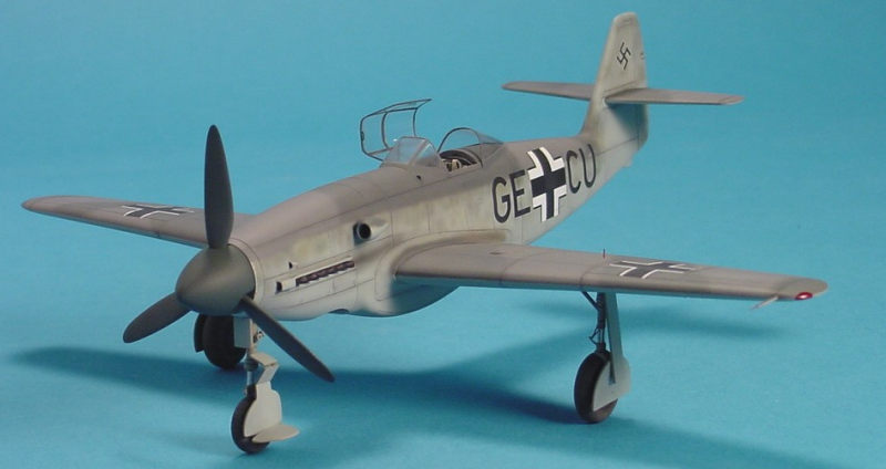
| NOTES: | Short run with resin parts and vac canopy. The later V1 variant, flown by Test Pilot Karl Baur, at Lechfeld Germany, in August of 1942. |
| HISTORY |
Messerschmitt began work on an advanced single-seat Me-309 fighter for the Luftwaffe in late 1940. Combat experience with Messerschmitt’s earlier Bf-109 fighter - which called for higher speeds, greater range, and heavier armament - was incorporated into this new design. This design also incorporated several advanced features, including a tricycle landing gear, a retractable radiator, a pressurized cabin, and ejection seat. Ten prototype aircraft were ordered from Messerschmitt in 1941.
Construction of the Me 309V1 (W.Nr/Factory Number 001, fuselage code
GE+CU) began in late 1941 and was completed in June of 1942. The aircraft was
powered by a 1750 horsepower (HP) Diamler-Benz DB 603A-1 12-cylinder,
liquid-cooled, inline engine turning a three-bladed, variable pitch metal
propeller. Taxi trials conducted in June and July of 1942 revealed a tendency
for the Me-309’s nose wheel to shimmy (m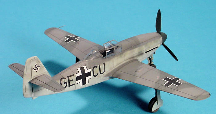 ove
side-to-side). After modifications to the nose wheel, Messerschmitt test pilot
Karl Baur made the Me 309V1’s maiden fight from Augsburg, Germany on 18 July
1942.
ove
side-to-side). After modifications to the nose wheel, Messerschmitt test pilot
Karl Baur made the Me 309V1’s maiden fight from Augsburg, Germany on 18 July
1942.
High-speed level fights demonstrated the Me-309V1’s directional instability, which resulted in enlarged vertical tail surfaces being fitted to the aircraft. Four different vertical tails were installed on Me-309s, yet handling problems persisted throughout its career. The fighter was also retrofitted with the 1475 HP DB 605 inline engine, which was installed on the subsequent Me-309 prototypes. An RLM pilot flew the Me-309V1 in a mock dogfight against a Bf-109G on 22 November 1942. This exercise showed that the Bf-109G could outmanoeuvre the Me-309, which had only a 30 MPH (48.3 KMH) faster speed than the older Messerschmitt fighter. The Me-309’s maximum speed of 360 MPH (579.3 KMH) was also 66 MPH (106.2 KMH) slower than the Focke-Wulf Fw-190D, which was under development in late 1942.
Four Me-309 prototype were built by Messerschmitt; the RLM cancelling the six other examples on order. The RLM cancelled the Me-309 project in 1943, due to the fighter’s lacklustre performance and technical difficulties.
| THE KIT |
I think it is beneficial as a modeller to stretch ones self occasionally
and try building something other than the oft-quoted Tamiya or Hasegawa "shake
and bake" kits. Truth be told, I find the term shake and bake to be insulting of
a modeller's abilities as it implies that no skill is required to build the
model. Well, I can tell you
 that I
have seen many of these supposed shake and bake kits that looked like crap once
finished. But, we will save this discussion for another day.
that I
have seen many of these supposed shake and bake kits that looked like crap once
finished. But, we will save this discussion for another day.
This model was my first foray into the Czech Model line of kits and I must say that I was pleasantly surprised with the overall quality and detail of the kit. It has a few little areas that require special attention and a few areas that I feel are incorrect, but none of these issues should deter you from tackling this kit.
Call me crazy, but the packaging of the simple black and white artwork with red accents really appeals to me. Inside this subdued box are 34 injection moulded parts on two sprues and a small bag containing 20 True Detail resin bits for the cockpit, wheel wells, wheels and exhausts, two vacuform canopies and a nicely printed decal sheet featuring markings for both the V1 and V2 prototypes coded GE + CU and GE + CV respectively. There is a little duplication between the plastic parts and the resin pieces in as much as the wheels are provided in both mediums.
| CONSTRUCTION |
First up, you need to decide if you wish to build the early or late V1, or V2 prototype, as some kit surgery is required for the early V1. Specifically, you need to remove the rear of the fuselage with the small vertical fin and replace it with a new section featuring the larger fin. I wanted to build the V2 as it displays the simplified late war crosses, which I feel are more attractive than the early two-tone crosses, but search as I might, I could not locate a photo of the V2. I only managed to come up with the same five images of the V1, so I settled on building the V1. Messerschmitt is supposed to have built four prototypes, V1 coded GE + CU, V2 coded GE + CV, V3 coded GE + CW and V4 coded GE + CX, but all you ever see is the V1.
When building a limited run kit, there are a few things that should be
done before you ever put paint to plastic. As locating tabs and bulkheads etc.
are non-existent, it is preferable to determine all your mounting points and
then attach some plastic strip to positively position the parts. Firstly, I
added some small pieces of strip styrene to represent the structural detail on
the cockpit sidewalls. These are p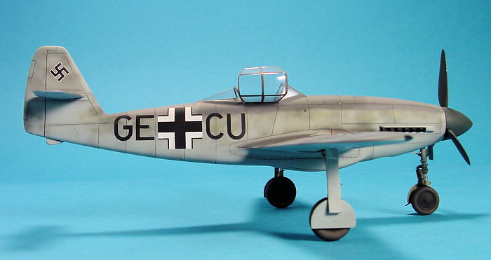 ositioned
to correspond to the panel lines on the exterior of the fuselage. Small pieces
of styrene were used to correctly position the cockpit tub. Finally, the way the
kit is designed, the exhaust manifolds are to be mounted from the inside, very
early on in construction. As this would just make the final painting more
difficult than it needs to be, I fabricated set of backing plates to allow the
exhaust to be inserted from the outside after final painting. This backing plate
served double duty, as I positioned it to also act as the locating tabs for the
nose wheel gear bay.
ositioned
to correspond to the panel lines on the exterior of the fuselage. Small pieces
of styrene were used to correctly position the cockpit tub. Finally, the way the
kit is designed, the exhaust manifolds are to be mounted from the inside, very
early on in construction. As this would just make the final painting more
difficult than it needs to be, I fabricated set of backing plates to allow the
exhaust to be inserted from the outside after final painting. This backing plate
served double duty, as I positioned it to also act as the locating tabs for the
nose wheel gear bay.
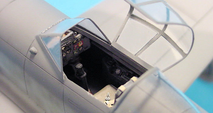
The cockpit was next and first up I tackled the instrument panel, which is a nicely cast resin piece and is usable as is. However, I do not like the way True Details provides the instrument faces, as I find they are just a deep hole with a real heavy dial pointer in the middle. So, I drilled out each instrument face and then after painting the panel in RLM 66 Schwartzgrau, the instrument bezels were painted with black, red, yellow and green. As this panel bears an uncanny resemblance to the panel found in the Me-262, and as references are almost non-existent, I painted it in the same manner as the Me-262. However, as I still had to replace those instrument dials that I drilled out, I used an old printed acetate instrument panel from the Eduard etch set for the Heinkel He-219. Rather than painting the backside of the acetate in white, I used a Liquid Paper Dry Line correction tape, as it does not need drying time and white paint will chip off the acetate when the dials are punched and installed.
The cockpit tub was airbrushed RLM 66, with semi-gloss black detail
painting. The seat which also looks like the same seat found in the Me-262 was
painted RLM 66, with Khaki coloured seat pads and a linen coloured seat belts. I
replaced my resin rudder pedals with a set of Waldron photo-etched pedals for no
other reason than the fact that I was too lazy to remove the resin pedals from
their casting blocks. The completed tub was fastened in place after first
sanding down the edges slightly to allow the fuselage halves to meet. The nose
gear well was installed as per the scribed line on the inside of the fuselage
and lead fishing sinkers have been epoxied in place to keep the nose gear on the
ground. I had a real strong bond, but
 unfortunately,
the wheel well was in the wrong place. If installed where Czech Model suggests,
the propeller will hit the nose gear on the completed model. I had to break the
epoxy bond and shift the resin wheel well back about 3/16". The only good thing
about this is that I discovered it before the fuselage halves were glued
together.
unfortunately,
the wheel well was in the wrong place. If installed where Czech Model suggests,
the propeller will hit the nose gear on the completed model. I had to break the
epoxy bond and shift the resin wheel well back about 3/16". The only good thing
about this is that I discovered it before the fuselage halves were glued
together.
I was now at what proved to be the worst part of the kit, which were the main landing gear legs. I found the mouldings to be somewhat undefined, which made clean up a chore. Also, both of my resin oleo torque links were broken beyond recognition. I replaced the links with some spare photo-etched parts and I fabricated the axles for mounting the wheels from some Evergreen rod. The gear retraction arms were detailed with some bolt heads made using my Waldron Punch and Die and glued to the main gear legs. I airbrushed Tamiya TS-14 Gloss Black on the oleo strut section of all the gear legs and once dry this was followed by a few light coats of Alclad II Chrome. I then masked off the oleos and proceeded to airbrush the gear legs with RLM 02, followed by a dark wash and then lightened RLM 02 dry brushing.
When I attempted to install the resin wheel wells in the wings it became quite obvious that they would not fit without considerable sanding to reduce their thickness. With wings assembled, I had two more steps to complete, one of which was optional and one mandatory. The optional step is to install some styrene strip to represent the wing structural detail that would be visible in the wheel well. The mandatory step was to glue in place a short section of plastic tube that was of the same diameter as the attachment points on the landing gear legs. I found this necessary, as there is no positive method of fastening the gear legs otherwise. Finally, there is a panel line missing from the bottom of the port wing.
Once these details are taken care of the airframe can be assembled, with
virtually no putty required, if you pay attention to the clean-up of the mating
surfaces and alignment of the sub-assemblies. There are small mounting stubs for
the tail planes and the fact that the main wings are merely a butt joint did not
pres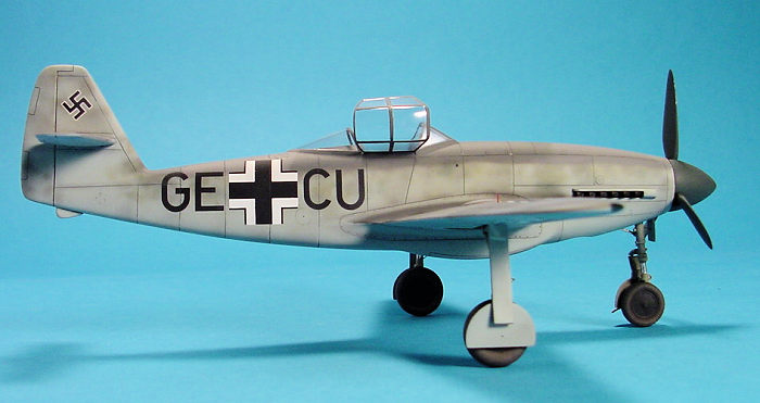 ent
any problems. The only problem I encountered with the assembly of the airframe
was the fact that some of the panel lines did not match from one fuselage half
to the next. This necessitated filling in some panel lines and rescribing new
ones, but again it was not a big deal.
ent
any problems. The only problem I encountered with the assembly of the airframe
was the fact that some of the panel lines did not match from one fuselage half
to the next. This necessitated filling in some panel lines and rescribing new
ones, but again it was not a big deal.
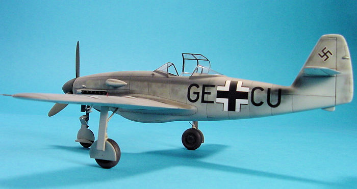
Next, it was on to the dreaded vacuform canopy. As a rule I will do my best to avoid working with a vacuform canopy, but in this case, I had no alternative. However, I am pleased to report that this was a canopy that actually fit the model. I think the biggest hurdle when working with a vac canopy is cutting them out properly. I know we all have our own techniques, or preferred method for removing them, but I will tell you how I do it. First, I outline, or define the outer edge of the canopy frame with thin strips of masking tape. It is far easier to cut along a line if you can clearly distinguish between the canopy and the excess plastic. Once cut out, I will sand the edges to shape the canopy so that it matches the contours of the fuselage. It is then glued in place with small drops of superglue. Next, I apply pieces of photographic splicing, or leader tape to cover the clear areas of the canopy. This is then followed by an application of Tamiya putty, or thick CA glue to blend in the canopy. I can then start to sand the seam. The green splicing tape is waterproof and thick enough that it protects the clear areas while I do all the bodywork. Once I am happy with the canopy, it along with the cockpit opening is masked off with Tamiya tape in preparation for the painting.
| COLORS & MARKINGS |
Painting was next and for this I airbrushed Xtracolor RLM 74 Graugrun and RLM 75 Grauviolett over RLM 76 Lichtblau, followed by a very soft and diffused mottle of RLM 02, 70 and 74. If I may stand on my soapbox for a moment, almost all models I have seen finished in the mid-war grey splinter scheme are incorrectly painted, in as much as the modeller has taken to heart the term 'splinter' and applied the RLM 74/75 with a hard edge. In reality, the demarcation between the colours should be soft edged. On pre-war aircraft, a true hard edge splinter pattern was in use, with straight hard-edged demarcations. This was in effect until 1939 when the camouflage started to change. From 1939 onwards, fighters employed soft-edged camouflage patterns, even if they were still called splinter. For the most part, bombers finished in RLM 70/71/65, and marine aircraft using RLM 72/73/65, were finished using the hard edge camouflage to the end of the war, with a few exceptions appearing on some late war bomber and maritime schemes.
The decals were next to go on and while they were well printed and in
perfect register, there were some errors. The upper wing crosses as supplied for
the V1 aircraft are identical to the fuselage crosses and are therefore
incorrect, as they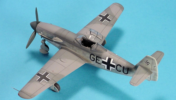 should have the reduced white areas. I base this on the good quality photo of
the Me-309, which is taken from the right rear where you can see the upper
surface of the wing. While I cannot state with 100% certainty, I feel the
fuselage crosses are a little oversize, but usable as they are. Once the decals
set up, a medium grey wash was applied to the panel lines and then I applied
trace amounts of silver paint to represent small chips, respecting the fact that
this was a prototype aircraft and would not have been subject to the same wear
and abuse as a front line fighter. This was all followed by a few applications
of Testors Dullcoat to achieve the desired sheen.
should have the reduced white areas. I base this on the good quality photo of
the Me-309, which is taken from the right rear where you can see the upper
surface of the wing. While I cannot state with 100% certainty, I feel the
fuselage crosses are a little oversize, but usable as they are. Once the decals
set up, a medium grey wash was applied to the panel lines and then I applied
trace amounts of silver paint to represent small chips, respecting the fact that
this was a prototype aircraft and would not have been subject to the same wear
and abuse as a front line fighter. This was all followed by a few applications
of Testors Dullcoat to achieve the desired sheen.
Czech Model does not indicate where the wingtip navigation lights should be situated, so I surmised that they would be similar to those found on a late model Bf-109 and masked off the areas where they would be. Then they were airbrushed with Humbrol Crimson and Xtracolor X320 Air Canada Teal. The pitot tube made from two pieces of hypodermic needles. You will notice in some references that drawings show the pitot tube mounted further inboard, but this is incorrect. The Me-309, like the 109, 110 and 262 had deployable leading edge slats that made it necessary to mount the pitot outboard of the slats. Landing gear position indicators were fashioned from piano wire, painted red and glued to the wings, the exhausts were airbrushed with Metalizer Burnt Iron and Burnt Metal and then slipped into position from the outside, while the hinged portion of the canopy was tacked in place with a few drops of super glue. All that remained was to apply some chalk pastel weathering and the model was finished.
| CONCLUSIONS |
This proved to be one of the most enjoyable kits I have built. There were a few minor nit-picks, but in the grand scheme of things, none of them were serious. Depending on the angle viewed, it either looks like an elegant racer, or it looks rather ungainly. But, no matter how you look at it, it is a good model of an interesting subject. Is it 100% dimensionally correct? I don't know and I don't care. I do not have plans to compare it to and if I did, I would be foolish to blindly assume the plans would be correct. All I know is it looks very much like the photos of the real thing.
Since I built this kit in 2007, the canopy has yellowed quite noticeably. If I were I to build another Czech Model kit, I would first make a copy of the vacuform canopy from a non-yellowing plastic.
| REFERENCES |
Historical narrative from the instruction sheet
Not much, aside from a few photos on the Internet and a photo in the Monogram Official Monogram Painting Guide to German Aircraft 1935-1945.
| FINAL CONSTRUCTION |
15 August 2017
Copyright ModelingMadness.com
If you would like your product reviewed fairly and fairly quickly, please contact the editor or see other details in the Note to Contributors.
Back to the Main Page Back to the Review Index Page Back to the Previews Index Page