Classic Airframes 1/48 Macchi C.200
|
KIT
#:
|
96-403
|
|
PRICE:
|
$30.00 MSRP in 1996
|
|
DECALS:
|
Two options
|
|
REVIEWER:
|
Andrew
Garcia
|
|
NOTES:
|
Short run kit with etched and resin parts. Vac canopy
|
The Macchi
C.200 Saetta, a term which I have seen translated into “Arrow and “Thunderbolt”,
was a radial engine fighter (also identified as the MC.200) built by Aeronautica
Macchi in
Italy,
and used in various forms throughout the Regia Aeronautica (Italian Air Force).
It had a distinctive cowl using the Magni-NACA separate streamlined fairings
over its rocker arms for maximum speed. It also had a distinctive copper surface
front cowl oil cooler. The MC.200 had excellent maneuverability and general
flying characteristics left little to be desired. Stability in a high-speed dive
was exceptional, but it was under armed with only two .50 cal fuselage mounted
guns and under powered.
 The first
prototype (MM.336) C.200 flew on
24 December
1937.
It was followed by the second prototype early the next year. During testing, the
aircraft attained 805 km/h (500 mph) in a dive, although it could achieve only
500 km/h (310 mph) in level flight due to a lack of engine power. Nevertheless,
this was better than the performance of the competing Fiat G.50, Reggiane
Re.2000, A.U.T. 18, IMAM Ro.51, and Caproni-Vizzola F.5.
The first
prototype (MM.336) C.200 flew on
24 December
1937.
It was followed by the second prototype early the next year. During testing, the
aircraft attained 805 km/h (500 mph) in a dive, although it could achieve only
500 km/h (310 mph) in level flight due to a lack of engine power. Nevertheless,
this was better than the performance of the competing Fiat G.50, Reggiane
Re.2000, A.U.T. 18, IMAM Ro.51, and Caproni-Vizzola F.5.
From the time
Italy
entered war on
10 June 1940,
until the armistice of
8 September
1943;
the C. 200 flew more operational sorties than any other Italian aircraft. The
Saetta ranged over
Greece,
North Africa,
Yugoslavia,
across the
Mediterranean
and
Russia.
Its very strong all-metal construction and air-cooled engine made the aircraft
ideal for ground attack and several units flew it as a fighter-bomber. Over
1,000 were built by the time the war ended.
The Saetta
underwent very few modifications during its service life. Aside from the switch
to an open canopy, it started out with an enclosed canopy (!); later aircraft
were fitted with an upgraded radio and an armored seat. Some late-production
Saettas were built with the MC.202 Serie
VII
wing, thus adding two 7.7 mm (.303 in) Breda-SAFAT machine guns to the armament.
The five
general versions of the C.200 were:
M.C. 200
(prototypes) - Two prototypes fitted with the 840 hp Fiat a.74 RC 38 radial
piston engine.
M.C. 200
various “serie” numbers for interim versions - Single-seat interceptor fighter,
fighter-bomber aircraft. This was the general production version. There were “serie”
modifications so use a reference photo because the use of prop spinners or no
spinner, covered and open canopy’s, a mass balance vertical tail versus a
straight tail surface, radios and no-radios, two types of props, and even some
wing guns when the C.202 wing was used on final production variants all come
under this “general production” version nomenclature.
M.C.200bis -
Breda-proposed modification with a Piaggio P.XIX R.C.45 engine producing 1,180
hp. His aircraft was a conversion from an early production C.200. It did not
enter production as the C.200 had been replaced by more advanced designs such as
the C.202/205 using the German DB series of inline engines.
 M.C.200AS –
this was an adapted version for North African Campaign featuring an underside
oil cooler in addition to the cowl ring cooler.
M.C.200AS –
this was an adapted version for North African Campaign featuring an underside
oil cooler in addition to the cowl ring cooler.
M.C.200CB –
the fighter-bomber version capable of carrying 710 lbs of bombs or two external
fuel tanks as a fighter escort for supply transports.
The Saetta was
to have been replaced outright by the C.202 after only one year in production,
but the C.200's service life was extended because Alfa Romeo could not produce
enough of the RA.1000 (license-built DB 601) engines, and more C.200s were built
using C.202 parts while waiting for production to increase.
Classic
Airframes (CA) released the Macchi C.200 in 1996. It was their third
release (# 403) of injection moulded kits. C.A. had previously established a
great reputation for finely made resin kits of inadequately or under represented
subjects. I enjoyed getting my hands on every Classic Airframes release and
admiring the multi-media (plastic, resin, white metal and etched parts) solution
to enhancing the details of 1/48th scale aircraft. The resin detail
parts were always amazing. The discontinuation of CA business operations was
truly a sad event.
This is my
first effort building a Classic Airframes (CA) kit even though I have every
release in my stash and have purchased them since 1995. I have a complete stash
of CA kits starting with the first release, Kit #401, of the injected CA kits
and I truly hope to build all of them. The additional effort required to clean
up the kits plastic, the dusty work with delicate resin and attaching some very
tiny etched metal parts has relegated some wonderful CA subjects to a permanent
future build status because they do take much more time to build than mainstream
plastic kits. For some modelers the need for constant dry fitting, sanding,
filing, and test fitting leads to incompletion. I know on this build the resin
cockpit fit gave me some concern. But - the future has arrived and I
 am now
building CA kits!
am now
building CA kits!
As a result
of a recent purchase of the Special Hobby 48033 Aermacchi C.200 I serie “Bubble
Canopy”, I was curious to see if the parent manufacturer MPM or Special Hobby
(SH) re-released the kit I already had as CA # 403 Macchi C.200. I am so
accustomed to the Hasegawa re-boxing process I expected to find the same plastic
and resins in both kits. The answer was - No, they are not the same kits. There
is a dramatic improvement in the injection plastic and some parts of the resin
in the SH kit. The SH 48033 kit is not a re-release of the old CA parts in any
way. The plastic and resin parts are totally different. The Special Hobby kit
has no etched metal and no white metal parts. The SH plastic is a decidedly
different plastic moulding and the resin while quite nice is not the same.
Back to the CA
# 403 Macchi C.200. Overall fit
is adequate and representative of roughly moulded limited run low-pressure
injection plastic, with a very low parts count. This makes for a simple assembly
process of the plastic parts. It also causes quite a bit of test fitting and
filing, as well as cutting and sanding preparation and final post assembly
sanding is required. There are several thick stubs on the inside of the plastic
from the mould release (punch-out) pins requiring a bit of cleanup. Surface
detail is reasonably refined and panel lines are thinly scribed in a petit to
scale manner giving a good impression in the box. It also looks good after the
kit has been painted and assembled. One vac-form canopy is provided. Mine has
not yellowed but I have seen several CA kit canopy turn amber yellow. It may be
tied to storage conditions since my kit has been in a cool dry location since
its purchase in 1996.
 The CA cockpit
resin is very nice. It stands the test of time and it is of equal quality to the
best aftermarket resin sets of today. I was very pleased with its appearance
after painting and dry brushing. There were moments when I struggled to attach
the many etched metal levers and “T-handles” thinking has anyone tried to do
this mating of tiny etched metal parts and resin before me? (Your
editor asked the owner of CA at one time if anyone actually built any of his
kits prior to packaging at release. I was told no as the folks who did the resin
and the folks who did the plastic bits are not even in the same city and the
resin folks never see the kit into which they are to be fitted. This, I was
told, was to prevent piracy. I also read on a forum that MPM's 'beginners' designed CA
kits due to the huge number, for a short run kit, that were produced. It also
was less expensive than using the 'first team'. It goes a long
way to explain why many CA kits are a b**ch to build.)
The CA cockpit
resin is very nice. It stands the test of time and it is of equal quality to the
best aftermarket resin sets of today. I was very pleased with its appearance
after painting and dry brushing. There were moments when I struggled to attach
the many etched metal levers and “T-handles” thinking has anyone tried to do
this mating of tiny etched metal parts and resin before me? (Your
editor asked the owner of CA at one time if anyone actually built any of his
kits prior to packaging at release. I was told no as the folks who did the resin
and the folks who did the plastic bits are not even in the same city and the
resin folks never see the kit into which they are to be fitted. This, I was
told, was to prevent piracy. I also read on a forum that MPM's 'beginners' designed CA
kits due to the huge number, for a short run kit, that were produced. It also
was less expensive than using the 'first team'. It goes a long
way to explain why many CA kits are a b**ch to build.)
I like having
the levers and “T” handles but there has to be some usability engineering
provided in the kit design. Some forethought into etched metal glue attachment
points would be a good change. I would appreciate some thinking going into ease
of attachment of these tiny bits. I do want and like to have these diminutive
details present on all my models. Resin or etched is the way to get there due to
injection plastic moulding limitations.
After all this
effort will I be able to see much inside a very small cockpit? After building
the kit the answer is not really. It is a small cockpit with an almost enclosed
canopy giving an encapsulated shape once the clear parts are attached so this is
not a big concern – just an observation or opinion. After all, if there is any
chance in seeing it I do want to detail it. It is an open cockpit so my
preference is to have every detail present and well finished. The combination of
resin and etched metal gives you that opportunity. I have to say Jules did a
superlative effort in detailing this kit with some excellent resin and brass
details. I am still impressed by his results, and this is one of the early kits.
There are
other ways to create a nice, improved, instrument panel and add some additional
cockpit detail. The alternative is to use the kit resin, some Evergreen plastic
and some punched–out aftermarket decals from Mike Grant for example for the
instrument faces. An interesting aside on the cockpit was my discovery of the
significant size difference when comparing the Classic Airframes cockpit length
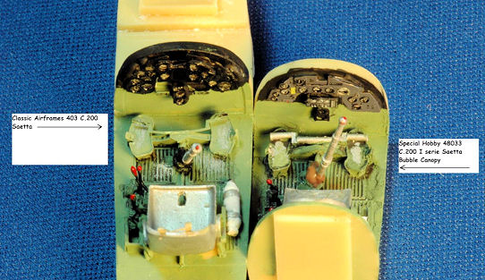
with the Special Hobby 48033 kit resin cockpit. The CA resin appears much more
detailed and is about two scale feet longer than its comparable Special Hobby
version.
For the other
teeny bits I prefer to do some drilling and add thin guitar wire rods with white
glue knobs as a somewhat easier way to detail the cockpit levers instead of
attaching minute flat handles and thin resin rods.
The Macchi
C.200 and 202/205 series have a unique seat belt arrangement. It appears the
C.200 only had a shoulder belt with a padded seat back/parachute pack. They all
appear to have a metal chain securing the seat belts or lower parachute backpack
to the cockpit floor. Also, the same chain arrangement appears to secure the
bottom of the seatback pad to the seat or floor as well. My point is there does
not appear to be the usual lap belts in this series of Macchi aircraft. The
chains are not represented in the CA # 403 C.200 etched metal. They do appear in
the Eduard etched sets for the C.202/205 and Italeri MC.200 kits etched sets.
The 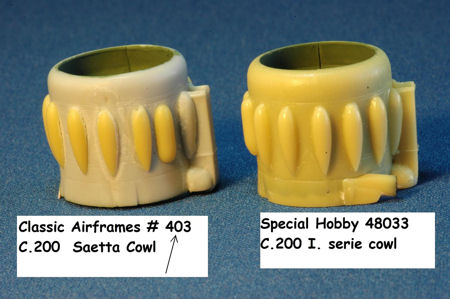 Eduard Zoom has both parts, the shoulder belt with chains and the floor to
seat chain restraining device. The CA resin seat has a hole to allow you to
thread the chain up from the floor through the seat bottom. The upper part of
the seat belts from the CA etched fret is adequate but missing the chains.
Eduard Zoom has both parts, the shoulder belt with chains and the floor to
seat chain restraining device. The CA resin seat has a hole to allow you to
thread the chain up from the floor through the seat bottom. The upper part of
the seat belts from the CA etched fret is adequate but missing the chains.
The engine
cowl is a two part injection plastic component. The front end is missing the
many facets from the corrugated copper oil cooling ring. A good photo will
disclose the oil cooling ring (a surface-type oil cooler, of soldered or brazed
construction using brass ribs) is made up of many small copper or brass wedges
or strips welded together with noticeable demarcations between the copper
strips. The CA kit plastic is a smooth surface. The corrugated nose finish would
have been better accomplished if the entire cowl had been cast in resin. No
aftermarket supplier that I am aware of issued any products to fix this area.
The seams created by a two part plastic cowl and having to attach the many resin Magni-NACA engine cowling valve fairings was not a good model design.
See the associated photo comparison of the CA cowl versus the Special
Hobby resin to get a better idea of the merits of each approach. It is a close
fit between the engine and cowl so be mindful when adding the resin cylinders to
the crankcase.
The kit decals
are printed by Propagteam. They are thin, nicely printed crisp graphics but
require some care when applying them since they tend to stick and not move when
applied. My previous experience with Propagteam decals like the ones with this
kit are they will resist relocation and not move once applied; unless you float
them on some saliva (water alone doesn’t work). I did not have any problems with
these decals, nor did I have to use the saliva application process to apply
them. I did use some Micro Sol “just in case” and they were so thin they look
great once they were applied.
In later years Classic Airframes changed
to using Microscale decals which are fantastic and at the end of CA kit
production, in 2008, CA was using crisply printed Cartograph decals. The kit has
a color decal placement and painting guide printed on glossy enameled paper
which is excellent. Jules produced a fine modeling package!
There are
other kits of the MC.200 Saetta now available such as the
Special Hobby # 48033 Aermacchi C.200 I
serie “Bubble Canopy”, Pacific Coast Models 48001 MC.200 Saetta Series
VII
(which I think uses the same Special Hobby plastic but adds etched metal parts),
and the two Italeri MC.200 releases. I have seen some modelers completed builds
of the Special Hobby, PCM and Italeri kits and they all look terrific. Also,
remember there have been resin kits available of the C.200 as well. Scott Van
Aken provided us with a great build of an Astrokit C.200 Saetta many years ago.
There is a
resin cockpit set from Pavla, # 48020, which is intended for the Italeri C.200
kit, which could be adapted to this model. I think the CA kit’s resin cockpit is
comparable and more than suffices for this kit. I have the Italeri kit and while
adequate a comparison of the Italeri cockpit plastic to CA resin parts has the
CA kit winning the detail contest but not the assembly effort comparison. I
found the CA resin cockpit to be somewhat more detailed than the newer Special
Hobby resin cockpit as well. The
 CA kit instrument panel was missing the
prominent Macchi cockpit feature of a bell-shaped Magnetic compass although the
hole for it existed in the etched metal parts PE12 and PE22 instrument panel.
CA kit instrument panel was missing the
prominent Macchi cockpit feature of a bell-shaped Magnetic compass although the
hole for it existed in the etched metal parts PE12 and PE22 instrument panel.
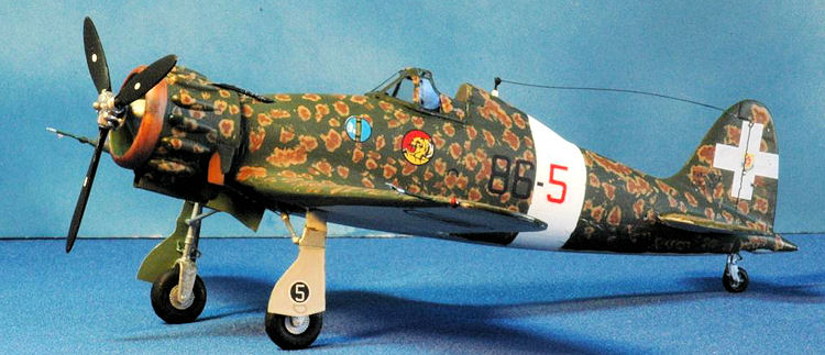
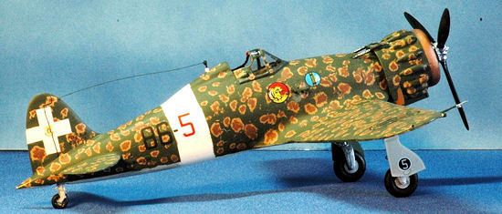
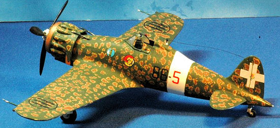
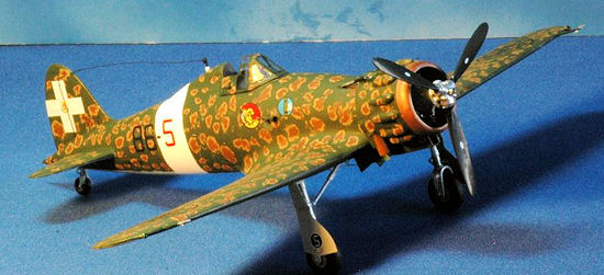
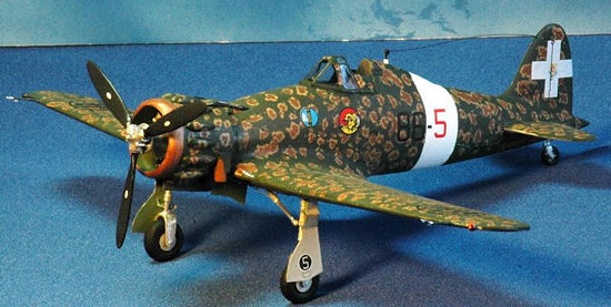
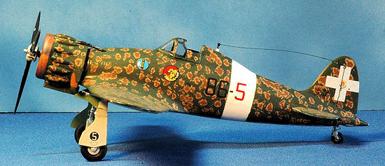
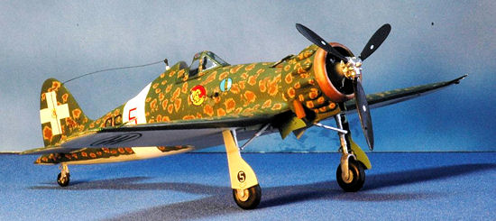
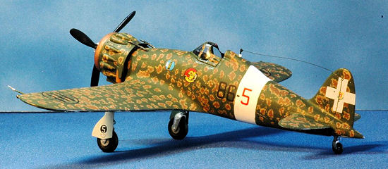
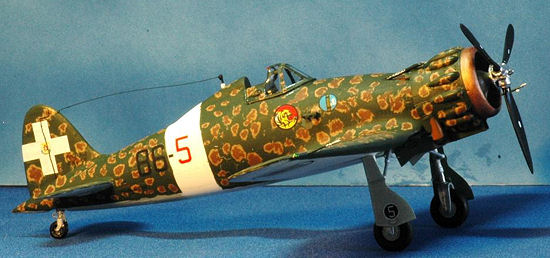
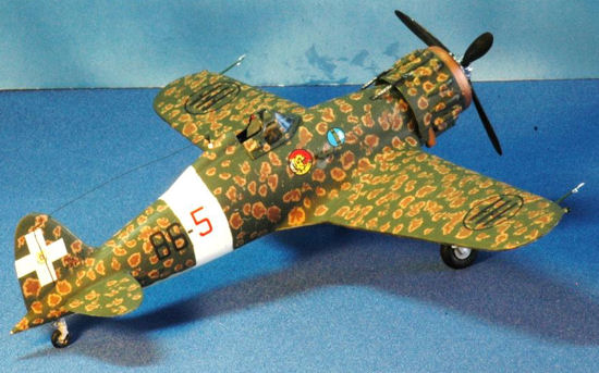
The kit
provided decals for two C.200 versions one in Sicily; 86th
Squadriglia, 7th Gruppo, 54th Sormo Caccia Terrestre,
1940-1941 Sicily, Italy and one in Russia; 369th Squadriglia, 22nd
Gruppo Autonomo Caccia Terrestre, 1941 Stalino, Russia
with the yellow cowl and fuselage bands typical of that theatre of
action. Both have the same essential color scheme of overall green “Verde
Mimetico 3”, with the patterned hazelwood brown “Giallo Mimetico 4” splotches
accompanied by smalled Bruno Mimetico splotches inside the Giallo.
I have the Sky Models 48-021 decal with
37 different C.200 options
which Scott used on his Astro Kit build. I learned quite a bit about the C.200
versions by closely examining the Sky Models profiles. It gave me some ideas for
future builds to get a complete set of all the versions of Macchi C.200’s! I
miss Skydecals too!
There are a pair of Tauro
Models decal sheets which could enhance painting of the multi-layer camouflages
for this aircraft, Tauro 48455 Amoebas and Worms Breda Style and 48457 Italian
Camouflage Breda Style 2 could be helpful for some of the complex camouflage
used by the C.200. Although not C.200 specific it looks like they could work on
some Italian aircraft schemes where finer air brush work would not be enjoyable
or attainable for most modelers.
As I
mentioned previously, this is my first build of a Classic Airframes kit. Since I
have done many conversions and added quite a few resin cockpits and etched bits
to my kits over the years there was nothing new or difficult with this kit.
There is just a lot of effort required to cut, shape and test fit, and then dry
fit all parts. Metal pins are recommended to improve the many butt fitted
contact points. Some of the plastic parts could be better detailed such as the
propeller hub so I added that to my construction plans. That could also be
looked at by a modeler as an opportunity to add some value through the
application of modeling skills and creative solutions rather than a boring
exercise in assembly.
 I started
the kit per the instructions which are easy to follow and well done. It consists
of six steps starting with the resin cockpit, step “A” and all its etched bits.
Inserting the completed resin cockpit tub and mating it to the sidewalls was a
modeling challenge. There are no locator pins or guiding marks so you are left
to you own resolution of what goes exactly where when it comes to adding the
completed cockpit tub. There is an odd fit where the seat back goes under the
rear cockpit wall where the armored headrest is located. I don’t think this is
what I have seen from the MC.200 cockpit photos. I built the Special Hobby and
Italeri kits in parallel to assist in kit comparisons and when compared side to
side the CA cockpit tube was quite a bit longer.
I started
the kit per the instructions which are easy to follow and well done. It consists
of six steps starting with the resin cockpit, step “A” and all its etched bits.
Inserting the completed resin cockpit tub and mating it to the sidewalls was a
modeling challenge. There are no locator pins or guiding marks so you are left
to you own resolution of what goes exactly where when it comes to adding the
completed cockpit tub. There is an odd fit where the seat back goes under the
rear cockpit wall where the armored headrest is located. I don’t think this is
what I have seen from the MC.200 cockpit photos. I built the Special Hobby and
Italeri kits in parallel to assist in kit comparisons and when compared side to
side the CA cockpit tube was quite a bit longer.
While doing this step I kept thinking
ahead to the step “F” process where the engine is mated to the fuselage. There
is not much room between the rear of the engine resin and the front of the
cockpit tub which forms the upper part of the landing gear bay. The cockpit tub
has a two part structure which includes the front wheel well detail. I used a
metal rod to support the attachment of engine core to the fuselage tub. While
this helped establish a secure join between the resin engine and the fuselage
you could mis-align the cowl unless care is taken with the metal pin attachment.
Once completed all the parts of the cowl did not line up. This area is where the
Italeri kit is a big improvement over the CA and SH kits.
The gunsight appears to be joined to the
instrument panel in Step “A” but its location and the actual rim of the cockpit
do not permit this to work. I added the gunsight after all assembly was
completed to the edge of the cockpit rim beneath the front windscreen.
The
gunsight is a nice resin casting but the clear portion, part # E, found on the
instrument panel acetate film, was incorrectly produced. It is a completely
blacked out segment instead of a black outlined part with a clear center
section. It looks like a misunderstanding between the designer of the parts and
the printer or manufacturer of the parts occurred. I worked around this by
cutting a piece from another part of the clear acetate film using the incorrect
part as a size guide.
The second
step, fuselage assembly, produced some problems. The fit of the upper wing to
the fuselage was off by about 1/16th of an inch. It is more than a
snug fit and I had to cut the upper wing mating surfaces where they touch the
fuselage after I glued the wings together. Sometimes this is caused by the
assembly approach or my incorrect assembly. That is, you could avoid this
mismatch by attaching the lower wing to the fuselage then fitting the two wing
top parts. A misfit is fixed by sanding the wing tips rather than cutting away
at the wing to fuselage mating surfaces. In the actual aircraft one wing is
intentionally longer. This was done to compensate for engine torque in the
C.200.
The
interior is the first part to be constructed. It consists of a seat, sidewalls,
instrument panel and control column. After painting a wash of dilute flat black
followed by some silver dry brushing left me pleased with the resin cockpit. The
etched metal seat belt once painted and glued onto the seat enhanced the
cockpit.
 Step “G”
(which you will find in a sub-box with step “B”) is the addition of the tail
wheel and its supporting plastic roof. A very nicely detailed resin rear wheel
is provided. I attached part 13 to one fuselage side first securing the plastic
part # 13 with plastic glue. When it was hardened, the next day, I used some
clear epoxy to provide a stronger join and reinforcement for this part since I
thought it might separate once the kit fuselage halves were closed and weight
applied to the rear wheel.
Step “G”
(which you will find in a sub-box with step “B”) is the addition of the tail
wheel and its supporting plastic roof. A very nicely detailed resin rear wheel
is provided. I attached part 13 to one fuselage side first securing the plastic
part # 13 with plastic glue. When it was hardened, the next day, I used some
clear epoxy to provide a stronger join and reinforcement for this part since I
thought it might separate once the kit fuselage halves were closed and weight
applied to the rear wheel.
I added a
small metal rod to this part by drilling a hole in the upper resin and gluing it
to the stirrup shaped lower resin fork. By using a very fine piece of guitar
wire the strength and rigidity it provides minimizes the potential of breakage
of a delicate and brittle resin part that will be subjected to unfortunate
handling or display impact. Because it is very thin it does not detract in a big
way but that is your choice since it does take away from the thin delicate resin
casting. An alternative is to drill through the resin from the top down into the
wheel and run the rod inside, essentially out of sight. That is the best
approach but requiring precision and patience that exceeded my goals for this
build. I wanted to see how the kit looked after the build before investing too
much time in a contest winner with fundamental flaws in shape or outline.
Obviously you could just leave it alone and hope the resin does not snap.
I thought
of varying from the kit instructions regarding installing the cockpit interiors.
It is possible to leave off the cockpit resin tub and install it after the
fuselage is joined together. I test fit this approach taping the fuselage
together and inserting the tub afterwards. You can do this if the wings are not
yet attached. This can be done as it is basically an open cockpit aircraft.
Once the
interior parts had been painted, the instrument panel was glued onto the resin
tub front bulkhead. I found the Evergreen styrene sheet, #9010 .010 inch, since
it is so thin yet mildly inflexible to be a good backing material for the etched
metal and clear acetate instruments Eduard instrument panel “sandwich” as well.
The newer
Eduard etched parts don’t need this white backing since the etched has the white
portions printed directly onto the etched parts.
I have not
had good results using etched metal with the clear acetate instrument backing
since they often look washed out or are barely visible or worse the glue and
white paint backing separate and the instrument panel comes loose during the
late stages of construction or after painting. I have started to use a white
styrene plastic sheet backing on the etched parts with a small application of
Gorilla Glue to get better results. The amount of glue applied has to be very
slight and very thin or you will not be happy with the results because it will
ooze and bubble when it cures. The best solution would be a new Eduard color
ZOOM
for all MC.200 1/48 kits since there are now Special Hobby, Italeri/Tamiya
releases as well that could benefit from the Eduard color zoom treatment. The
biggest contribution the Eduard etched makes is for the replacement instrument
panel and seat restraining chain with seat belts in pre-painted color which
Eduard does so well.
 The
completed resin cockpit kept shifting when I tried to add it to the fuselage. I
was never 100% sure it was in the right place. There is a small diagram in the
instructions, step “S” that combined with the diagram for step “B” completes the
mating of the seat with its harness and resin cockpit tub.
The
completed resin cockpit kept shifting when I tried to add it to the fuselage. I
was never 100% sure it was in the right place. There is a small diagram in the
instructions, step “S” that combined with the diagram for step “B” completes the
mating of the seat with its harness and resin cockpit tub.
The cockpit
to fuselage mating was not a happy event. The kit engineering is lacking in this
area. I would have enjoyed having some type of pin or protrusion on the inside
of the fuselage to indicate proper cockpit tub placement prior to sealing things
up. Through test fitting, more cutting and trial and error it worked. The
difficulty is enhanced though the addition of resin part PU6 which is the wheel
bay interior detail since PU6 attaches to the front of the cockpit resin tub.
Why weren’t these two parts cast as one unit? Although I enjoyed the modeling
challenge of this limited run kit and love the subject matter, the cockpit
assembly and integration into the fuselage plastic was difficult and annoying.
I actually
had a moment where I thought it would be a better idea to take a Hasegawa C.202
kit and attach the CA kit radial front end as an easier way to get a happy
modeling experience because I had set it aside a few times as a no fun exercise
frustrated by the cockpit positioning and alignment problem. But, I really
wanted to complete the build so I made it work basically by grinding away at
some of the resin cockpit components and jammed it in. This only worked because
it is a small cockpit and you don’t see much once it is inserted. For this part
of the build Slo-Zap thick and slow curing Cyano Acrylate (CA) glue was my
friend! Once all the sanding, grinding and repeated dry fitting was over I used
the thick slow curing cyano glue to hold the cockpit walls in place. I had to
use a Dremel micro router bit to cut back some interior resin to permit the trim
wheel area to fit. The Slo-Zap was instrumental in solving the “how do I get
parts that don’t click together and have no locator pins to stay in place”.
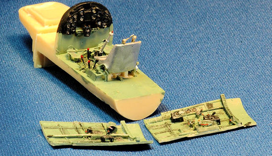
I used the
Panaflex vise as a part holder (see photo) for much of the cockpit assembly. By
placing the resin cockpit at the correct angle the part would stay in place long
enough to allow the slow cure to work and fill some of the small gaps created by
the cutting and trimming dry fitting process. I had to deviate from the
instructions by gluing plastic part # 14, which is the top front of the
fuselage, to the left fuselage in order to ensure the resin cockpit tub and
resin cockpit walls would fit. The rear of part # 14 is part of the fitting
requirements and in step “B” of the instructions.
The final
procedure I settled on was gluing the right sidewall onto the cockpit tub. Once
this was dry I test fitted the tub with one sidewall by closing the two fuselage
halves. I then attached part # 14 to one of the fuselage halves. Once dry I
glued the other cockpit wall in place test fitting it to ensure it would close
together. I used Slow-Zap CA to secure the cockpit and some masking tape to hold
the fuselage parts together. A few Berna clamps were also used and I waited
until things set overnight. The next day I glued the remaining cockpit wall in
place using a few metal clips along the top to attach them to the plastic
fuselage. The cockpit wall was essentially held in place by the glued in tub
before this step.
I gave up
on trying to insert a completed cockpit tub up through the opening where the
wings would go due to the shifting tub problem. There is a potential concern
with part 14, which is the top front section of the fuselage resulting in large
gaps on both sides. A kit designer has many choices to make and some have both
positive and negative impact. In this case part # 14 leaves large rough seams on
two sides of the front fuselage nose section. The alternative would have been to
mould the fuselage into two halves without this extra section. The SH kit for
example followed the alternative and was much easier to assemble, eliminating
the putty and sanding exercise that occurred with the CA kit.
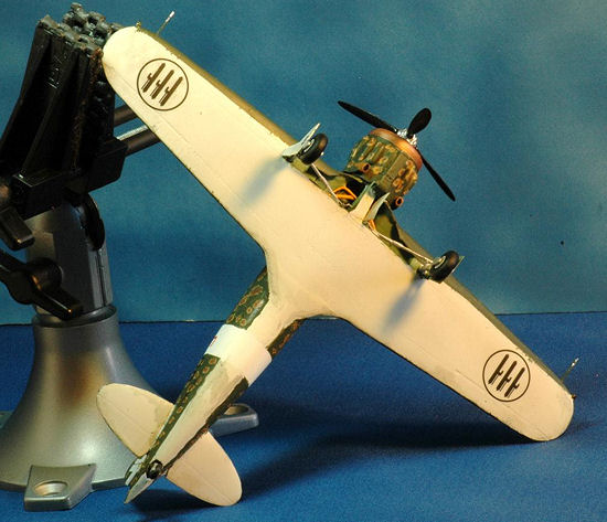
The wings
were cut to fit within the fuselage width space. What this means is they did not
fit and it required some cutting and modeling effort to have the wings mate (see
photo). Since they are plastic I used plastic glue to close the seam up. I
noticed the actual aircraft has a prominent wing tip light with the inner orb
(the side facing the pilot) painted so that it creates a half-shell light which
helps others in formation without affecting the pilots night vision. The wing
lights are represented as two very small bulges in the kit wings. Due to the low
pressure roughly moulded plastic one wing tip light was partially sanded off by
accident when I was preparing the wings by sanding off the many rough plastic
bumps. I took two straight pins (the type without the pearl heads)
 and inserted
them in the area on the wing tips that had a small bulge. The Special Hobby
48033 kit has a better crafted wingtip light by the way.
and inserted
them in the area on the wing tips that had a small bulge. The Special Hobby
48033 kit has a better crafted wingtip light by the way.
Once the
wings were on, it was time for the tail section. The vertical fin/rudder was
part of the fuselage plastic part # 1. I used a few light applications of Aves
Apoxie Sculpt filler to blend it in since there was a gap on the starboard side
fin to fuselage join that using plastic cement did not fill. After this step the
horizontal stabilizers were glued in place. I used pieces of metal straight pins
to attach the horizontal stabilizers and make a firm bond since they are butt
joins.
The next
step, “C”, which is the undercarriage was a bit problematic. The locating holes
and end part of the landing gear mating was not very secure. Essentially, the
mounting of the white metal parts to the wing landing gear cavity was a
challenge requiring care and patience. I used epoxy on this part as well and
used the Panaflex vise with rubber jaw guard to hold the kit upside down to
permit this slow bond to work. I then added some Aves Apoxie Sculpt around the
top of the landing gear leg, inside the gear cavity to secure it even further –
it just seemed too fiddly without this extra effort.
The inside of the main gear well of an
actual C.200 is highly detailed with exposed parts, pneumatic hoses, cables and
wires. CA provided a number of etched parts for detail in this area but they are
mainly for the landing gear. This misses the need for the hoses and wiring that
are the bulk of the details.
Since it is
quite open and exposed with a lot of plumbing you can super detail this area if
you wish. I used the kits resin and etched metal and placed a few pieces of
copper wire and bass guitar wires for the hydraulic hoses and electrical wiring
and called it a day. This is an ideal place for a multi-part resin enhancement
since color photos on page 60 and 70 of the Macchi C.200 SAETTA, Orange Series #
8113, Stratus Books, Mushroom Model Publications reference show the complexities
of this area. The CA kit is partially missing the tubular support structure
which is another prominent feature and part of the SH kit. The CA kit has the
lower tubular section represented in a 2D manner in the landing gear bay resin
roof. This section is also simplified in the Italeri kit. Special Hobby has the
tubular parts in its design but also is lacking in the other details.
While all
this was going on, during the paint drying wait time, I worked on the engine
cylinders and cowling as they are the next steps, items “D” and “E”. The CA
cowling is a very interesting piece of work. It consists of two halves with no
blisters. You have to remove the NACA blisters from their resin carriers and
then attach them to the plastic cowl. I thought it would have been much better
to have a one piece resin cowling with the NACA blisters already there as is
found on the Special Hobby release. Aligning the plastic cowl halves, parts 5
and 6 is also a challenge because there are no locator pins. The kit
instructions show the cowls with the blisters on in the first page kit contents
diagram. In step “E” you are challenged to attach the blisters and join the cowl
halves. I taped the cowl halves
together and started by only gluing the ends. Once this set, the next day, I
removed the tape and re-glued it inside and outside. Later the next day I
started to fix the seams. Once this was completed it was time to remove the NACA
blisters from the resin pouring blocks and attach the resin blisters to the
plastic cowl. There are two blisters which are not as tapered (parts PU 2) that
go on the top. Once painted it does
look very nice much to my surprise.
I cut and
glued on each cylinder to the main engine block using metal straight pins as
connectors with some cyano glue for the join. This may not be necessary but I
have never had a cylinder come off with the rough handling caused by inserting a
very tight fitting engine into the cowl such as with this assembly. I detailed
the engine by adding spark plug wires and also using plastic rod for the
cylinder push rods instead of the etched metal part # 16. I thought at first
this etched metal part was the ignition wiring harness because it was similar to
those found on many Eduard etched metal sets as a wiring harness.
After
looking at some photos of the actual aircraft in an Italian museum it seemed it
was intended to replicate the prominent pushrod sleeves. I left it, the kit
supplied etched part off because it looked too flat and was not a drop fit after
I test fitted the etched part. The plastic rod looked much better. I would have
appreciated it if the resin cylinders had this, the pushrod sleeves, moulded on.
 The Special
Hobby kit, # 48033 is also missing the prominent external valve pushrods. The
Italeri kit does a good job with this section providing the pushrods attached to
the front and rear of the engine crankcase along with the engine exhaust piping.
Also, looking at the museum aircraft it seems the wiring harness is behind the
engine and not in a ring at the front as is usually found in American radial
engines so it would not be accurate to add a wiring harness to the front end so
I believe the etched was intended to represent the pushrod sleeves.
The Special
Hobby kit, # 48033 is also missing the prominent external valve pushrods. The
Italeri kit does a good job with this section providing the pushrods attached to
the front and rear of the engine crankcase along with the engine exhaust piping.
Also, looking at the museum aircraft it seems the wiring harness is behind the
engine and not in a ring at the front as is usually found in American radial
engines so it would not be accurate to add a wiring harness to the front end so
I believe the etched was intended to represent the pushrod sleeves.
The gun
troughs are only a starting point and need to be opened.
The resin machine gun tubes were too plain for me to use. They are
lacking the air cooled perforations. It would have been perfect to have the
resin tubes plus a perforated etched metal cooling jacket. I substituted the
Quickboost QB48342 MC.200 Saetta Gun barrels resin replacement set. Although it
is for the Italeri kit it is adaptable to this model. It appears in later
MC.200’s the extended blast tubes were removed, similar to the MC.200, serial #
M.M. 7707 which is a late serie
VII
airframe, found in the Museo Storico dell’ Aeronautica Militare Italiana. An
alternative was to use the Master model AM-48-054 Breda Safat 12.7mm brass gun
tubes for the resin tubes provided with the kit. The Master brass guns are
stunning. There is no comparison to a resin moulded gun tube – they are that
much better. The brass looks much better and compared to just using regular
brass tubing there is no comparison with the drilled cooling jacket and gun tube
insert Master model provides. However, since this kit has a few shortcomings
induced by my modeling skills, I opted to use the Quickboost part and save the
Master gun tubes for another build. The CA supplied gun barrels are simple tubes
and just need to be drilled out. I saved them for another day.
The front
cowl addition was glued in place but it was a very careful process since the
first time I tried to fit it onto the engine a few pushrods were knocked loose.
It is a tight fit but it does work. I also secured the engine and cowl to
the fuselage by inserting a metal rod into the rear of the resin engine and
mated it to the tip of the cockpit tub.
I used the kit
supplied decal for an aircraft from the 86th Squadriglia, 7th
Gruppo, 54th Stormo Caccia Terrestre 1940-1941 based in Sicily,
Italy. I initially chose the second color option for the 369th
Squadriglia, 22nd Gruppo Autonomo Caccia Terrestre, 1941 Stalino,
Russia because the yellow cowl bands are so colorful. Since I will be building
the Italeri C.200 and that kit has a similar (not identical) marking for a 369th
Squadriglia, 22nd Gruppo aircraft I went with choice “A” in the CA
kit.
The C.200 had
three general types of camouflage color schemes, mottled, desert and single
color. Within these classes are four mottled subtypes, three desert subtypes and
two solid color schemes. I recommend you get the
Mushroom Publications No. 8113 book for
a complete description of these. They are very interesting camouflages and a
wonderful challenge to paint. The alternatives make for very attractive
finishing options. Mushroom Publications book made this part a reality – no more
wrong guesses! The superb Aero Detail # 15 book also has camouflage color
information on page 65 but it was simplified compared to the expanded coverage
in the MMP book. The Mushroom Publications No. 8113 book has a very detailed
expansion on the camouflage schemes, especially the mottled ones on page 10,
which I found most helpful.
Once the white fuselage
band was painted and masked off, the underside of the wings and tail planes were
painted Grigio Mimetico (light grey). I used Tamiya acrylic colors for this as
they are called out including mixes in the instructions for a Tamiya released
version of the Italeri C.200 kit. I looked up the instructions online and felt
more confident using the Tamiya acrylics for this project.
 I initially
chose to model the plane from the 369th Squadriglia, 22nd
Gruppo Autonomo Caccia Terrestre, 1941 Stalino, Russia with the yellow cowl,
under wingtips and fuselage bands because it is very colorful. A profile of it
can be found on page 86 of the Macchi
C.200 Saetta Orange Series # 8113 Mushroom Publications book and a similar
aircraft is in an Italian aviation museum with some fine photos available on the
web for this color scheme. However, since I plan on building several versions of
the MC.200, I went with the first color scheme in the CA color guide for
the 86th Squadriglia, 7th Gruppo, 54th Stormo
Caccia Terrestre aircraft. Regrettably
the color profiles are small and that made it difficult to match but having them
is a great help and much better than what most other kits offer. Again I
complement Jules B. on putting all the pieces needed together in one package.
Remember, most Regia Aeronautica aircraft like the MC.200 had the upper wing
color wrap around the leading edge about 6 to 8 inches underneath the wing.
I initially
chose to model the plane from the 369th Squadriglia, 22nd
Gruppo Autonomo Caccia Terrestre, 1941 Stalino, Russia with the yellow cowl,
under wingtips and fuselage bands because it is very colorful. A profile of it
can be found on page 86 of the Macchi
C.200 Saetta Orange Series # 8113 Mushroom Publications book and a similar
aircraft is in an Italian aviation museum with some fine photos available on the
web for this color scheme. However, since I plan on building several versions of
the MC.200, I went with the first color scheme in the CA color guide for
the 86th Squadriglia, 7th Gruppo, 54th Stormo
Caccia Terrestre aircraft. Regrettably
the color profiles are small and that made it difficult to match but having them
is a great help and much better than what most other kits offer. Again I
complement Jules B. on putting all the pieces needed together in one package.
Remember, most Regia Aeronautica aircraft like the MC.200 had the upper wing
color wrap around the leading edge about 6 to 8 inches underneath the wing.
The cockpit
and wheel wells of the C.200 were painted in a color which comes from my
declining stocks of AeroMaster paints (# 1120 U.K. Interior Green Acrylic). The
instructions indicate to use light grey. I chose to use the same color as the
aircraft from the two museums I reviewed prior to building. However, some of
those photos also show a light grey was used in portions of the lower cockpit
areas such as the floor, rudder pedals and lower cockpit walls. The Tamiya
instructions indicate XF-21 Sky and XF-5 Green in a 50% each mixture for the
cockpit. This mixture provides a color similar to the U.K. WWII color of
interior green or cockpit light green.
For the
overall fuselage finish I used Tamiya acrylics. The exact colors used were XF-59
Desert Yellow, XF-52 Flat Earth, and XF-67 NATO Green. The undersides are a mix
XF-2 Flat White (66%) and XF-66 Light Grey (34%) for a very light grey
underside. It was easy to use and the results good with a fast drying time and
no masking pull-up losses. I added some black to the light gray to dirty up the
undersides with some patches or streaked areas. I used Aves Apoxie sculpt to
fill in any gaps such as the wing to fuselage join, and the top of the fuselage
front end. I try to use water and my wet finger tip for most of the gap repairs
when I use Apoxie to avoid sanding away surface details. It is also faster and
easier with an excellent ability to blend in without leaving a seam. Try it you
will like it!
Weathering
and Final Coat – some pastel chalk and black/brown pin wash was used. I sprayed
on a Testors gloss coat to prep for decals and Dull Cote to seal in all the
decals instead using the Future coat used during the initial application to seal
all of the decals.
The props
have a decal stencil which looks more like the Hamilton-Standard emblem than the
Macchi emblem decal on the props. Although the prop is a Piaggio P.1001
propeller it has the Macchi logo on the prop. Take a look at the prop stencils
from the Hasegawa Macchi Mc 202 kit and from the Skymodels decal sheets and
Italeri kits as an example of this logo. The Skymodels sheet for the MC.205
properly shows the two different propeller types (labeled Macchi & Breda)
similar to that used by the C.200 one of which was actually a license built Fiat
Hamilton-Standard 34DI-1 prop hence the similar shaped decal used in the kit and
the other a Piaggio P.1001 prop which was the most commonly used prop on the
C.200. An excellent description and drawing of the prop logos is found in the
Aero Detail # 15 book on page 71. A comparison, drawing and description of the
propeller is found in the Aero Detail # 15 book on page 78. Since the license
built Fiat Hamilton-Standard 34DI-1 prop was only used on the first 25 serie I
units the correct logo is usually the Macchi emblem. The prop hubs also have a
different shape and there are balancing weights on the Fiat Hamilton-Standard
34DI-1 prop hub. The stencils came from the kit decals as well but there were
only a few to apply.
The last
part, Step “F” (Final assembly) consisted of adding the cowl, prop and prop
boss, canopy, twin machine guns, twin wing pitot tubes (PE47) and venturi tube
(PU16). The prop and prop boss plastic were a bit rough and required some clean
up especially to get the very prominent three bolts that secure the prop to the
rear hub to look good. The center of the prop hub is a prominent feature. It was
missing from the plastic prop. I used a clothing straight pin with a small pearl
top as the missing hub tip and as a connector to the resin radial engine. First
I drilled a hole into the resin engine, then using the same diameter drill bit
drilled though the plastic parts 15 and 18. This permitted a good alignment and
a secure bond. By using a pin that had a pearl head I added some
ZAP
CA glue to the tip to fill in the bottom of the pin head. I held it upside down
in an alligator clip device while it dried in an effort to reconstruct the
noticeable end point of the C.200 prop assembly which is missing from the kit
plastic.
I used a
Dremel to hollow up the exhaust stacks, parts # 16 & 17 added in step “E”. I
used a brush and two step process for painting the exhaust pipes. I brushed on
Metalizer Dark Iron non-buffing. When it was dry I used some thinned Pactra IP96
Rust enamel as a wash. Many photo references show the C.200 Saetta exhaust were
painted the same color as the fuselage camouflage colors so you have a choice to
make.
The CA kit
part, PU13, which is a small antenna mast was added at this point. Some clear
sewing thread was used for the antenna wire which was then painted flat black
and attached using gorilla glue. There were three types of communications used
by C.200 pilots resulting in three choices for the modeler. Some aircraft had no
radio using the time honored hand signal methods from WW I and the Spanish Civil
War. Some C.200’s had radios. The radio’s used a small antenna behind the pilot
headrest and some of the antennae’s were connected via a wire to the leading
edge of the vertical stabilizer. I have also seen pictures and a even a color
profile found on page 13 of Macchi C.200 Saetta Orange Series # 8113 Mushroom
Publications using a three point antenna wire configuration attached to the
wings in an arrangement similar to a P-40. This configuration appears on some of
the initial aircraft that were outfitted with radios.
 The C.200
has an unusual double pitot arrangement featuring a pitot rod on each wingtip.
The reason for this is one pitot is heated and the other is not. It also has an
unusual cranked upward step with a second small tube under the main tubular
component. CA faithfully reproduced this but it is in flat etched metal. I took
some guitar wire and attached the flat etched metal to it to improve
survivability of this part and also add a “3D” depth to the flat part. I glued
the etch to the guitar wire, added some CA glue to round it out and painted it.
Some C.200’s also appear to have two piece straight tubular pitot’s as well
which I rarely saw in wartime photos. This type of pitot, the simple straight
version is available with the QB48341 Quickboost MC.200 Saetta Pitot Tubes &
Antennas resin. I am not sure how many of these, the straight pitot rods, were
used compared to the cranked one but you will find them both appearing in the
Italeri kits with the cranked pitot on the early fuselage versions and the
straight one in the later version.
The C.200
has an unusual double pitot arrangement featuring a pitot rod on each wingtip.
The reason for this is one pitot is heated and the other is not. It also has an
unusual cranked upward step with a second small tube under the main tubular
component. CA faithfully reproduced this but it is in flat etched metal. I took
some guitar wire and attached the flat etched metal to it to improve
survivability of this part and also add a “3D” depth to the flat part. I glued
the etch to the guitar wire, added some CA glue to round it out and painted it.
Some C.200’s also appear to have two piece straight tubular pitot’s as well
which I rarely saw in wartime photos. This type of pitot, the simple straight
version is available with the QB48341 Quickboost MC.200 Saetta Pitot Tubes &
Antennas resin. I am not sure how many of these, the straight pitot rods, were
used compared to the cranked one but you will find them both appearing in the
Italeri kits with the cranked pitot on the early fuselage versions and the
straight one in the later version.
The landing
gear covers should have a slight bend in order to conform to the tire hump and
wing airfoil shape whereas the etched parts are flat. I used the Special Hobby
Kit # 48033, plastic parts 5 & 6 as the template to shape and form the curve
needed for the flat CA kit etched parts. The curves caused some problems with
attaching these parts so I had to rework things. Adding the etched covers was a
challenge due to the added etched metal attachment points but once done they
look very good and are very accurate with an in-scale look. You do have to be
very careful with these since the etched attachments that hold the covers onto
the landing gear are difficult to glue. I could have done better with mine
placing them a bit lower since it was a learning experience on how to best
attach these. There are no tail wheel doors on this late version of the C.200.
The resin tail wheel is very well casted and well represented.
The clear
vac-form parts were added using Testors 8876C white glue. I use this because of
its long, tapered black plastic applicator that allows small amounts to be
carefully placed. The radio mast and antennae wire was attached using some cyano
to hold it followed by a micro dab of gorilla glue and painted as the last step.
My windscreen clear part was clear and not yellowed. I have seen many CA kits
experience a yellowing of the clear parts. Perhaps storage temperatures have an
effect on long term canopy glass vac-formed parts. I have read where the
material for vac-forms will yellow with time. Mine were still transparent with
no discoloration. I have read the solution is to use PETG plastic for vac-formed
canopies available from K&S plastic. A
spare canopy from the SH kit might help if your kit has this problem. Falcon and
Squadron vac replacements do not appear to be available at this time. There is a
fantastic piece of etched metal, part # PE 29 which is the canopy hood release
latch in step “Z”. What an amazing attention to detail Jules brought to this
model!
The copper
radial oil cooler was painted using Tamiya dark copper XF-28. If you like a
shinier surface you can try titanium gold or even gold with some dry weathering
dry brushing. I liked the Tamiya dark copper shade since it approaches the tone
of a slightly weathered copper visible on the many WWII era color photos of the
C.200.
The C.200
has a small tail light. I painted this silver with a small white dot in the
center. Once the paint was dry I added a drop of clear epoxy to the tip to
simulate the light cover.
The CA
cowling was not up to the high quality of the rest of the kit. The copper cowl
ring is poorly represented lacking in the fine lines representing the brazed
copper panels of the oil cooler ring. There is a notch in the top rear portion
of the plastic cowl parts. I could not determine if it was for ease of
attachment, or an actual nuance of the aircraft cowl or just missing another
component to permit a flap in this section. From reviews of actual aircraft
photos I feel it is a missing part (or I was too eager to cut away at the
plastic when removing it from the trees and notched it by accident). A piece of
kit supplied etched would have been appropriate. There was none and no plastic
part so I used some Evergreen white styrene # 9010 .010 ( i.e. .25mm) inch
thickness sheet to create the missing top of the cowl flap. The part goes on the
cowl between the gun troughs. There may be an etched metal part for this not
called out in the instructions but I found none. The gun troughs are only a
starting point and need to be opened prior to painting. Once the kit was painted
the cowl looked very good so it is not my intent to say the cowl ruined the kit.
It just made it harder to build and introduces some alignment problems with the
armament and lacks the center tab.
There is a
very noticeable seam in the middle of the cockpit armor plate section. I cut a
piece of evergreen sheet plastic and added it to the headrest area. It
covered up the seam and added the missing pilot armor plate. The armored
headrest area is very nicely represented in the Italeri kit # 2676, in part
number 18A.
I really
enjoyed building the Classic Airframes C.200 Saetta. Any comments made were just
modeler musings and sharing building tips in addition to identifying areas of
improvement for scratch builders. While it is not a shake and bake two day build
like the Italeri kit, the challenges were overcome with the application of
modeling skills. I have a few more CA Saetta’s in my stash and look forward to
building them as well to make some other versions of the Saetta appearing on the
Skymodels C.200 decal sheet. The colorful camouflages and paint variations of
the Macchi C.200 Saetta make for a superb painting canvass. The references I
mentioned will be of great help.
 The cockpit
is hardly visible since it is a small opening so don’t fret too much about the
inside appearance – just get the seatbelts and seat looking good and you should
be happy. I do hope to see others build this kit and the Special Hobby 48033
Aermacchi C.200 I serie “Bubble Canopy”,
Pacific Coast
Models 48001 Mc.200 Saetta Series
VII,
and the Italeri/Tamiya C.200 releases. I have seen some modelers completed
builds of the Saetta’s from Special Hobby, PCM and Italeri kits and they all
look terrific. It is a small sized aircraft so it won’t take up too much shelf
space. It does stand out in a crowded shelf since the random visitors
(non-modelers) that look at my built kits often ask “what is that” and “what a
cool paint scheme” so it is an interesting aircraft for the casual observer.
The cockpit
is hardly visible since it is a small opening so don’t fret too much about the
inside appearance – just get the seatbelts and seat looking good and you should
be happy. I do hope to see others build this kit and the Special Hobby 48033
Aermacchi C.200 I serie “Bubble Canopy”,
Pacific Coast
Models 48001 Mc.200 Saetta Series
VII,
and the Italeri/Tamiya C.200 releases. I have seen some modelers completed
builds of the Saetta’s from Special Hobby, PCM and Italeri kits and they all
look terrific. It is a small sized aircraft so it won’t take up too much shelf
space. It does stand out in a crowded shelf since the random visitors
(non-modelers) that look at my built kits often ask “what is that” and “what a
cool paint scheme” so it is an interesting aircraft for the casual observer.
The kit did
take a bit of extra effort to complete since it is multi-media. It is an
impressive package for the price producing a very nice looking model. I have
read reviews where some feel the outline is not quite right but after building
it and looking at a lot of references it passes the mark 8 eyeball display test.
While building it I wondered why Hasegawa hasn’t produced the C.200 using parts
from their C.202/C.205 family which are beautiful kits. After building this kit
it would seem a resin conversion set producing the radial front end mating it to
the rest of the Hasegawa plastic could have provided an easier to build kit.
However, the availability of the Italeri kit reduces the probability of this
occurring.
All my
concerns should be taken with a constructive spirit of how to make the most out
of this kit rather than focusing on any serious shortcomings. I am pleased I
built it, enjoying the journey to build the kit and look forward to building
some more of the CA Saetta’s. When I look at the portfolio of kits Classic
Airframes released and the amount of modeling satisfaction from building unique
or non-mainstream subject matter aircraft they provide I sincerely thank and
appreciate what C.A. did for all of us! Sometimes it takes a limited run,
multi-media kit to get all the details right.
Macchi
C.200 Saetta, Orange Series # 8113, Stratus Books, Mushroom Model Publications
2012
Aero Detail
# 15, Macchi C.200/C.202/C.205 Dai Nippon Kaiga, August 1995
C.200 Saetta Scale
Aviation Modeler International Vol. 2 # 8 August 1996
AeroMaster decal # 48-154
Macchi C.200 Saetta
SKYModels decal # 48-021
Macchi C.200 Saetta
Andrew Garcia
January 2013
If you would like your product reviewed fairly and
fairly quickly, please
contact
the editor or see other details in the
Note to
Contributors.
Back to the Main Page
Back to the Review
Index Page