| KIT #: | 61034/80329 |
| PRICE: | 150 / 180 DKK |
| DECALS: | |
| REVIEWER: | Nicolai Plesberg |
| NOTES: | Techmod 48018 decals |
| HISTORY |
Initially designed as a biplane, to replace the successful F3F Navy biplane fighter, the XF4F-1 was on the drawing board altered to a monoplane fighter as the XF4F-2, to follow the new trend in the mid 1930s of replacing biplane fighters with monoplane ones. Although the XF4F-2 flew well it did loose out to the XF2A-1, which became the Brewster Buffalo as the Navy’s first monoplane fighter.
However, the performance of the XF4F-2 had convinced the Navy that it did possess development potential and therefore encouraged Grumman to continue development. Grumman went back to the works and took the opportunity to replace the engine, the Pratt & Whitney R-1830-66 Twin Wasp, with a more powerful variant, the R-1830-76 equipped with a two-stage supercharger providing 1200hp for take-off as the R-1830-66 had only got 1050hp available for take-off. The wing span was also increased and to ensure lift of the heavier aircraft the rounded wing and tail plane tips were abandoned and “squared” instead – which inevitably became a Grumman trademark.
The
XF4F-3 as the altered aircraft was designated flew for the first time on 12th
of February 1939 and later that summer Grumman was awarded a contract for 54
F4F-3 production machines. France placed an order of 100 planes, but the order
was diverted to Great Britain as France was overrun and occupied by the Nazi war
machine in May-June1940. The new Grumman fighter was named Martlet in Royal Navy
service, but named Wildcat in US service, had several engine changes and cowling
flaps modifications during its service life due to cooling problems of the
engine. The wings were non-folding, which initially caused some concern in the
US Navy as it’s usual for naval fighters to have a wing folding mechanism to
save space on crowd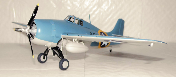 ed carrier decks. The armament of the Wildcat / Martlet
consisted of 4 cal. 50 machine guns, but that was considered too light by the
Royal Navy, as they wanted more punching power when facing their German and
Italian opponents, so Grumman was asked to take these concerns into
consideration.
ed carrier decks. The armament of the Wildcat / Martlet
consisted of 4 cal. 50 machine guns, but that was considered too light by the
Royal Navy, as they wanted more punching power when facing their German and
Italian opponents, so Grumman was asked to take these concerns into
consideration.
The result of Grumman’s efforts was the F4F-4 variant with manually folding wings and with the R-1830-86 variant of the Twin Wasp engine. The armament had also been increased to six cal. 50s, but this feature was not welcomed by the pilots (the actual users of the planes!) as the weight of the two extra guns had made the Wildcat more sluggish in handling and also slightly slower than the F4F-3 variant. On top of that the ammunition for each gun had been decreased to save weight. The pilots much preferred the longer firing time of four guns than the increased firepower of six guns.
When World War II began on 7th of December 1941 in the Pacific the US Navy had two monoplane fighters, the Brewster F2A Buffalo and the Grumman F4F Wildcat. When faced with the onslaught of the Mitsubishi Zero it was clear that both American fighters were inferior and could not beat the Zero in dogfights. The Buffalo was a dedicated death trap against the Zero; the Wildcat suffered too at the beginning, but soon, after a hard learning curve of heavy casualties and the introduction of new combat tactics, Wildcat pilots soon began to score some victories against the Zero and a few pilots even obtained ace status. Also the rugged construction of the Grumman fighter, known as “Grumman’s Ironworks” enabled the Wildcat to endure heavy battle damage and still be able to fly the pilot back to base even if it had been shot to shreds.
As the Wildcat did seem to hold the superior Japanese at a distance, it was decided to develop a fighter which would be able to surpass the Zero’s performance. Grumman was already in the work of doing just that with the project that resulted in the superior F6F Hellcat. To speed up the development and production of the Hellcat so it could enter combat service as early as possible, it was decided in April 1942 to transfer production and future development of the Wildcat to Eastern Aircraft, the aircraft division of General Motors. From here F4F-4 production continued now under the new designation FM-1. The only alteration that Eastern Aircraft did to the F4F-4 airframe was to remove the two outer guns and restore the ammunition capacity for the four remaining guns to please the wish of many Wildcat pilots.
Eastern
later substituted the Twin Wasp engine with the more powerful and lighter weight
Wright R-1820-5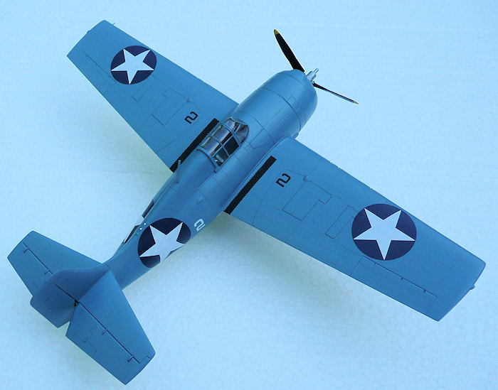 6 Cyclone in a shorter cowling, as the Cyclone was a single row
radial engine taking up less space in longitudinal direction than the two-row
Twin Wasp did. To counteract the increased torque from the more powerful engine,
Eastern found it necessary to increase the height of the fin and rudder so
directional stability could be restored. This variant was designated FM-2 and
became the most widely produced version of the Wildcat with more than 4400
leaving the production line and making up nearly 60 percent of all combined
Wildcat variant production figures.
6 Cyclone in a shorter cowling, as the Cyclone was a single row
radial engine taking up less space in longitudinal direction than the two-row
Twin Wasp did. To counteract the increased torque from the more powerful engine,
Eastern found it necessary to increase the height of the fin and rudder so
directional stability could be restored. This variant was designated FM-2 and
became the most widely produced version of the Wildcat with more than 4400
leaving the production line and making up nearly 60 percent of all combined
Wildcat variant production figures.
Even after the service entry of the Hellcat and Corsair in 1943, Wildcat production was continued, because it was considered an invaluable asset, primarily as it was found to be well suited to operate from the myriad of escort flattops that were constructed during 1942-45 and which were too small to operate the Hellcat and Corsair from their substantially smaller decks. Later the Wildcat’s roles became more of supportive character than as fighter, as it was assigned to the hunt for enemy submarines, as well as participating in bigger amphibious operations such as Operation Torch in November 1942, the Allied invasion of North Africa. When production was terminated by VJ-Day, more than 7800 Wildcats of all versions had left the production lines; the majority of them build by Eastern.
| THE KIT |
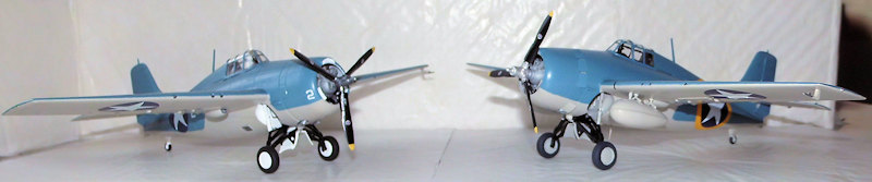
Tamiya:
This kit is typical Tamiya: well engineered with an excellent fit and superior to all former Wildcat kits in this scale. However, two errors (a rare thing with Tamiya kits but there you go) must be dealt with. The first relates to the raised rivets that almost the entire exterior surface is festooned with. Although the Wildcat did have raised rivets in real life Tamiya has just exaggerated their size. They need to be sanded down or else decaling would be difficult indeed; sanding them down will provide the best solution to get decals in place without the risk of tearing them apart.
The second error relates to the cockpit floor. The Wildcat was equipped with two lower fuselage windows to provide downwards view for the pilot, but if the kit was the real plane the pilot wouldn’t be able to see a thing through them! In other words the plastic areas between the instrument panel bulkhead, foot troughs and the seat bulkhead must be removed in order to make see through possible. The assembly of wings and tail planes to the fuselage are straight forward as alignment are build into the parts.
Hobbyboss:
When I
opened the box it struck me that the layout of the parts was very similar to the
Tamiya kit. As I already had build the Tamiya kit before buying this one, I was
not able to do a full parts up comparison, i.e. fitting a upper wing with a
Tamiya lower wing, a right fuselage half with a Tamiya left one etc., but the
outline of both wings and fuselage seemed very similar; only Hobbyboss’ wing
tips are a bit rounder than Tamiya’s, but that should be easy to deal with if
you possess some experience. The tips of the propeller blades
 are also a bit
pointier than on the Tamiya propeller, but the best way of dealing with that is
either to ignore it or replace the propeller completely, since modifying the
tips is difficult indeed (ask me how I know!).
are also a bit
pointier than on the Tamiya propeller, but the best way of dealing with that is
either to ignore it or replace the propeller completely, since modifying the
tips is difficult indeed (ask me how I know!).
For some odd reason the cowling flaps has been molded in open position – this will require some surgery if one wants to close them. And now when we are at the engine surroundings; the kit is supplied with two intercoolers molded together, but as my understanding of this, is, that the F4F-4 did only have one intercooler. How this is going to be dealt with, I honestly don’t know because they are connected to the structural tubing in the gear bay. Of course it could all depend on if some exact photos of the gear bay of a surviving example could be available so this arrangement could be examined in detail and then reproduced correctly, because I don’t feel convinced that Hobbyboss has done it quite by the book here; but it could as well be a consequence of multiple versions from the same mold – it’s seen before.
The hinges for the elevators are full represented in the Tamiya kit, but only vaguely in the Hobbyboss kit, but that should also be relatively easy to deal with. In return the Hobbyboss kit is more detailed in the gear bay; the oil tank for the engine and some more of the supporting structural tubing are included and the cockpit floor is correctly done. The surface detail consists of engraved lines and rivets (although this may be considered an error, since the real planes had raised ones) which seems to be close to scale. Anyway in some ways the engineering is different from the Tamiya kit regarding alignment of the wings and tail planes but that shouldn’t pose any problem for the average experienced modeler.
Techmod Decals: The reason for buying this sheet was the fact that the Tamiya kit, which I bought second hand, had been exposed to moisture and the decals were suspicious as some of the roundels had lifted from the sheet! In order to use more of this excellent sheet, I bought the Hobbyboss kit; I was aware that the wings needed to be modified to the six gun layout as the decal sheet provides only six options for the F4F-4 variant.
| CONSTRUCTION |
Tamiya:
The show started by removing the larger parts plus the interior parts from the sprues and, after cleaning them up (removal of sprue gates, mold lines etc.), gluing the left console together. Then I removed the aforementioned areas of the cockpit floor, first by cutting with the razor saw a bit out from the bulkheads until just before the foot troughs. The knife was used to cut along the foot troughs until the two areas simply snapped off; a file was then used to clean the edge roughness to a level where sanding sticks of various finer grades took care of the rest. The interior parts plus the fuselage halves were then cleaned thoroughly to remove any sanding dust / grease or other dirt that might affect the adhesion of paint. The interior was then painted Bronze Green (Humbrol 75) and required two coats to be perfect covering. The gear bay plus the inner side of the cowling was painted Flat White together with some smaller details in the cockpit and also required two coats to be perfect. The cockpit and gear bay was detail painted accordingly to my references.
When all paint had dried up, the interior was glued together and the wings and gear legs were also assembled. The fuselage halves were also glued together at this stage. While all this was drying, the engine parts were cleaned up and painted. The cylinders and crankcase went a grey metallic color with strays of a more burned shade on the cylinder heads. Some black was also used in between and the ignition wires on the forward cylinder bank went gold color; the rear bank didn’t have them, but as it would be difficult to see them anyway I didn’t bother to replicate them. After painting was finished the engine was assembled and put aside to dry.
 The gear
was painted satin black on the lower parts and flat white on the gear legs
themselves. The wheel hubs also went flat white and tire rims flat black. Now I
did an alteration, because the engineering is made in such a way so the wheels
can actually made to turn if you want that feature. The procedure is as follows:
when wheel hubs and the rims of the tires have been painted as described above
attach the inner parts of the wheels onto the axles and simply flare the axles
over with a hot knife or other suitable tool. Then glue the wheels together,
sand down the seam and paint the rest of the tires. With a little caution the
wheels can now turn depending on the precision of your efforts.
The gear
was painted satin black on the lower parts and flat white on the gear legs
themselves. The wheel hubs also went flat white and tire rims flat black. Now I
did an alteration, because the engineering is made in such a way so the wheels
can actually made to turn if you want that feature. The procedure is as follows:
when wheel hubs and the rims of the tires have been painted as described above
attach the inner parts of the wheels onto the axles and simply flare the axles
over with a hot knife or other suitable tool. Then glue the wheels together,
sand down the seam and paint the rest of the tires. With a little caution the
wheels can now turn depending on the precision of your efforts.
At this stage I glued the interior plus the rudder to the fuselage. When dry the fuselage seam needed some sanding but also slight small amounts of filler were necessary to get things all blend in. The wings and tail planes were next; glued on the fuselage and when dry, treating the seams the same way as before. The oil coolers were glued to the wings at this stage.
After dealing with the last issues on the airframe (such as sanding down all the raised rivets or at least most of them), the propeller shaft was glued onto the propeller. The hub went steel, blades went satin black and tips went yellow. The blades were decorated with some stencils I found in the dungeon and after securing them with some satin varnish the propeller was finished and put aside.
The last things missing were the final bits to the cockpit plus the clear parts themselves but that was easy meat and after stuffing the holes for the external fuel tanks, as I wasn’t going to use them, the complete surface was washed. After gluing the gear in place the airframe went off to the paint shop.
Hobbyboss:
The Hobbyboss kit was done in about the same way, but as I had learned something from my Tamiya build and also because the kit should be modified to the F4F-4 variant, I took a slightly different approach to this one.
As
I had removed all the bigger parts (fuselage and wings) plus the parts for the
interior and cleaned them up the interior went about the same coloring as my
Tamiya kit did. Before painting though, I carefully masked off where the gluing
surfaces of the bulkheads in the fuselage halves should be, because I did not do
this on the Tamiya kit, as it had been a pest to scrape off the paint from the
gluing surfaces in the fuselage halves as the bronze green paint just about went
all over the place and I was determined
not to repeat that
success!! It is also important to paint every single part of the interior
separately,
because it will be too difficult to paint when things have been glued together
first. If that is done in this sequence, you will be rewa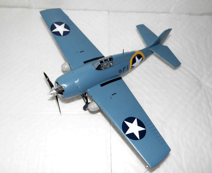 rded of your work as
the detailing of every part is top notch.
rded of your work as
the detailing of every part is top notch.
While the work of the interior was underway, I also began working on the wings. The two extra machine guns, which was the difference between the F4F-4 and FM-1 dictated that:
inspection hatches on top of the wings should be scratched in and hinges added
raised panels for the lower side should be added
the ejection chutes for the spent cartridges should also be scratched in / material removed so there was a depth visible
bulges for the outer guns should be added
To ensure doing it properly I decided all these modifications should be done prior of gluing the wings together. As I had my finished Tamiya model to use as guide it was fairly simple to scratch in the hatches on the upper surfaces on the wings. The hinges located in the front side of the hatches were made of an exceptionally fine piece of stretched sprue and glued carefully in place; not too much glue here please! The effect of this detail is rather astonishing.
The ejection chutes were next; scratched the outline of them in first then digging a little deeper with the knife to remove some material. As they are going to be painted black anyway, how they exactly look down at the bottom is less important, as the black paint will effectively hide it. The raised panels for the underside were simply a piece of the thinnest card I had on stock (0.3mm) cut to size and glued in place. As they were a bit too thick, I sanded off material until the thickness matched the panels for the inner guns. A sanding stick is ideal for this job. The bulges were produced from a couple of scrap plastic bits, which were glued to a piece of thick stretched sprue to act as a handle. The bulges were simply sanded to shape and when finished cut off from their handles and glued in place on the wings.
The next task is to glue the machine guns in place. You don’t have to scratch the two extra guns as there are six of them included on sprue F in the kit. The first four guns are easy; just glue them to the holes indicated for that purpose, but the two outer guns….. well first you need to make the opening of the leading edge of both top and lower wing half – easy done. Then drill some locating holes in the lower wing halves (just don’t drill through the wing!); precision is here important. After drilling the holes, which were barely a half millimetre deep, I got my outer guns in place so after painting them (optional as only the blast tubes are visible)and opening the holes for the oil coolers, the wings were glued together. The fit was exceptionally good; no real filler was used in the seams; only some “glue filling” and a light sanding on all the seams made the wings finished quickly. Though I also did modify the wing tips, so they looked more correctly squared with the help of some plastic bits cut into shape and glued to the wing tips. Then it was a matter of a couple of filling / sanding sessions so they matched the shape of the wing tips on the Tamiya model.
As described before the tips of the propeller blades are pointier than the prop in the Tamiya kit. Apart from that the prop is actually quite good so I decided to leave it as it was. The hub went silver, blades satin black and blade tips yellow. Some Curtiss Electric prop logos from a Yellow Wings sheet went on to beef up the prop blades. They were sealed in with satin varnish and the finished prop put aside.
When fitting the interior to the fuselage it is recommended by the instructions to glue it to the bottom fuselage piece, but due to my dry fitting tests, I decided to glue the interior to the left fuselage half as it would be easier to get a better fit this way. The gear bay interiors were done in parallel to the cockpit, but unlike that, it was painted Grumman Grey, more precisely my rendition of it; Humbrol 129. Apart from the bronze green cockpit the rest of interior surfaces were painted this primer color by Grumman. So I painted gear bay, gear legs, wheel hubs and the inner side of the cowling this grey color – another new thing that I’ve learned and Tamiya did not catch, since they advised flat white in these areas, as I had done on my model, too. But I wasn’t ready to do that mistake again! The only things that didn’t get painted grey in the gear bay area was the oil tank (which went yellow), the chains for the gear retraction system (which went burned /oiled metal) – think of the color of a bicycle chain – that must be appropriate, and the intercoolers for the engine which went a grey metallic color (although the grilles went silver) and the lower part of the main gear that went satin black. When finished the gear bay interiors were glued to the bottom fuselage section as advised in the instructions – it seemed reasonable to do so.
The last
to be done before the fuselage halves could be glued together, was to attach the
tail gear plus the arrest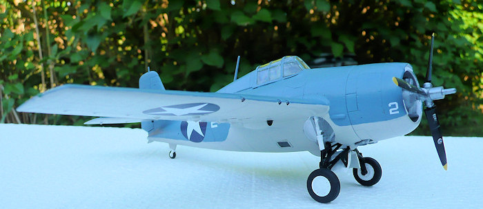 er hook. After the tail gear was painted; grey for the
fork / hub and tire black for the tire, the tail gear was glued to the left
fuselage half. The arrester hook was glued in place as soon as the head had been
painted metallic grey. Then the fuselage halves were glued together and the
bottom fuselage section was attached to the joined fuselage halves with adhesive
tape (and a couple of clamps to the fin) to ensure proper alignment during the
drying of the fuselage halves.
er hook. After the tail gear was painted; grey for the
fork / hub and tire black for the tire, the tail gear was glued to the left
fuselage half. The arrester hook was glued in place as soon as the head had been
painted metallic grey. Then the fuselage halves were glued together and the
bottom fuselage section was attached to the joined fuselage halves with adhesive
tape (and a couple of clamps to the fin) to ensure proper alignment during the
drying of the fuselage halves.
When the glue had dried up I removed the clamps and the tape, but as almost is the case the seam required some reinforcement in shape of slow drying CA glue in the places where the plastic glue apparently didn’t bond the two halves properly. Some touch up of the interior colors also became necessary, but as soon as these things were done, I began to adapt the lower fuselage section as it did not quite fit properly as intended. Some material was removed from the bulk head and other places where the fit was very tight but in the end I got an almost “ slip on” fit of the lower fuselage section; then it was glued to the fuselage and tape kept it in alignment until the glue had set. Also in this case some reinforcement with slow drying CA glue on the seams became necessary to get a stronger bond all around. The seams were then treated with sanding and slight doses of filler here and there – the fit is pretty good but not like Tamigawa.
When the fuselage had been finished, the wings, tail planes and rudder went on. Unlike Tamiya, Hobbyboss have chosen to make the wings in separate units; despite this alignment went surprisingly easy although some sanding in the left wing root was needed, since the dihedral angle on the left wing was greater than that on the right wing and as the right wing looked correct this was the way to go. The fit of the tail planes was so tight that alignment was no problem here either.
After the obligatory seam treatment of wings and tail the rest of the build went quite along the same lines as the Tamiya kit had been done. As soon as the last things such as the oil coolers, the clear parts and main gear had been glued in place the model went to the paint shop.
Well, one note regarding the main gear assembly sequence (also valid for other Wildcat kits with a similar parts engineering): when fitting it to the gear bay it should be without the gear doors glued in place because then it will be difficult to attach the gear fairing (part F23 in this kit). The gear doors should also be reversed as the instructions are incorrect. Finally it would be a good idea to have painted the fairing and gear doors before they are glued in place to avoid any difficulties later during painting!
| COLORS & MARKINGS |
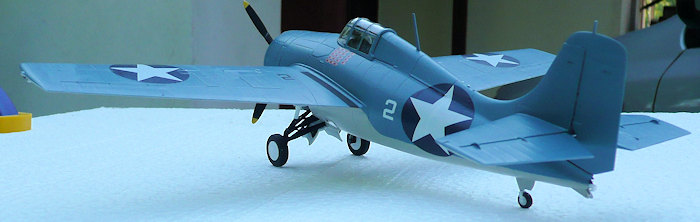
Tamiya:
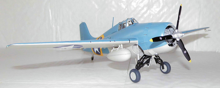
The under surfaces were painted grey (Humbrol 129) as this grey color is pretty close to the light grey color used by the US Navy until early 1943. Two coats were needed to cover perfect. The sides and all upper surfaces were painted U.S. Navy Blue Grey (Model Master 2055) also needing two coats to cover perfect. Some small touch up sessions became necessary but not the usual amounts so I guess I was kind of lucky. A gloss coat sealed everything and at the same time preparing for the decals.
I had chosen to model the aircraft of Capt. Marion E. Carl from VMF-223 at Guadalcanal in September 1942. Carl was one of the great Wildcat aces and one of the very few US fighter pilots to survive the Battle of Midway – remember that Japanese Zeros swept away all air opposition in this battle with ease. This intrigued me to model his Wildcat, as it was a fine example of that the Wildcat, in the right hands, could be successful and inflict casualties among the superior Japanese.
The decals, as I told you about earlier were razor thin, actually the thinnest
decals I have ever worked with so far, but plenty of water and a few Tamiya
cotton buds did almost the job for me. It is crucially important
not
 to touch the decals themselves with the fingertips – use a Tamiya cotton bud or
a similar object to handle them. The insignia on the fuselage gave a little
trouble due to the curves, but in the end I got them to conform to the surface.
to touch the decals themselves with the fingertips – use a Tamiya cotton bud or
a similar object to handle them. The insignia on the fuselage gave a little
trouble due to the curves, but in the end I got them to conform to the surface.
Before sealing in the decals I attached most of the final bits such as the antenna mast behind the cockpit, the pitot tube and the exhaust stubs. They were painted their respective colors and I also painted the blast tubes of the machine guns burned metal. As this had all dried up the entire surface was given a gloss coat to seal everything in and also get a uniform surface before applying the final flat coat.
The absolute finals consisted of gluing the approach and landing lights in place, marking of the position lights and painting the ejection chutes of the spent cartridges plus walk ways flat black. The walk ways were carefully masked off then acrylic flat black paint was applied and the tape removed immediately after the last brushstroke to avoid any edges. The last action was to squeeze the propeller in place and my Tamiya Wildcat was finished.
Hobbyboss:
The paint scheme was quite similar to my Tamiya build, as I had chosen to model the aircraft of Lt. Cdr. John Raby from VF-9 aboard the USS Ranger during Operation Torch in November 1942, so as before the under surfaces went grey (Humbrol 129) and sides and upper surfaces Blue Grey (Model Master 2055).
After the obligatory glossing the decals went on. The first problem I encountered was when the fuselage roundels were applied; they simply wouldn’t conform without making wrinkles. I applied MIG decal softener, but it didn’t really seemed to help much, so I took a brand new scalpel blade and carefully slit up the wrinkles. That was a lot better as all the wrinkles virtually disappeared! The problem was due to the extra large size of the roundels because of their yellow outline, which was an Operation Torch special recognition feature (compared to the smaller size roundels applied to the Tamiya model).
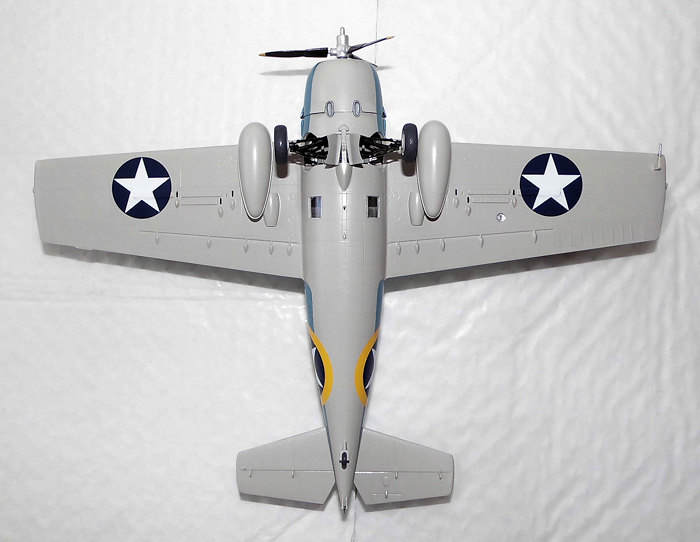
The second problem I had, was, that I was actually the roundels for the upper sides of the wings short, as the four that were present on the sheet had been used on my Tamiya model. However, there were two more roundels in the same size; only they had the red dot in the middle, which was abandoned in May 1942. I produced two disks of white decals, which went over the red dots and voila – a better solution could not have been achieved although the disks were a bit thick, but that only shows up close. Some flat white acrylic color was used to even out the disk edges to sort of camouflaging their presence.
Final bits were pretty much the same procedure as my Tamiya build.
| CONCLUSIONS |
So what is the conclusion of all this? Boy, that’s a tough nut to crack because both kits have their advantages. I think that this is the kind of conclusion where it all ends up with the taste of preference, because, in my view, there is really no definite “winner” of this build. It is entirely up to you which kit to purchase because I can’t really say “that’s the one to buy”. They both go really well together and there are really no snags that an average experienced modeler can’t solve regarding the few issues that both kits have (but what kit hasn’t?!). The choice is yours.
| REFERENCES |
Osprey Modelling Modelling the F4F Wildcat By Mark Glidden © 2007 Osprey Publishing ISBN 978-1-84603-110-6
http://en.wikipedia.org/wiki/Grumman_F4F_Wildcat
26 July 2016
Copyright ModelingMadness.com If you would like your product reviewed fairly and fairly quickly, please
contact the editor or see other details in the
Note to
Contributors.