Monogram/Koster 1/48 XP-47J Superbolt
| KIT: | Monogram/Koster 1/48 XP-47J Superbolt |
| KIT #: | ? |
| PRICE: | ? |
| DECALS: | ? |
| REVIEWER: | Dale Rannals |
| NOTES: | Conversion |
| HISTORY |
The fastest version of the Thunderbolt was the XP-47J, which was proposed in November 1942 as a lighter-weight version of the Thunderbolt designed to explore the outer limits of the design's basic performance envelope. This was a completely new airframe and not a conversion of an existing P-47D. The serial number was 43-46952. The ventral intake for the CH-5 turbo supercharger was separated from the engine cowling and moved aft. The four-bladed propeller was fitted with a large conical-shaped spinner. The wing structure was lightened and the armament was reduced from eight to six 0.50-inch machine guns. The contract was approved on June 18, 1943.
The XP-47J flew for the first time on November 26, 1943. On August 4, 1944, it attained a speed of 504 mph in level fight, becoming the first propeller-driven fighter to exceed 500 mph. At one time, it was proposed that the J model would be introduced onto the production line, but the advent of the even more advanced XP-72 resulted in plans for the production of the P-47J being abandoned before any more could be completed.
The
XP-47J was fitted was fitted with a high output version of the P&W R-2800.
Specifically, the R-2800-57. This engine made 2,800 hp @ 2,800 rpm at 35,000
feet. This is in War Emergency Power. The aircraft actually attained 507 mph at
an altitude of 34,300 feet. 2,800 hp is actually 133% of rated power. At
military power (100%), the XP-47J could still sustain 470 mph. 435 mph was
attained at “only” 81% of its rated power (1,700 hp). All performance figures
were obtained at 34,300 feet. The "J" model was an especially good climbing
fighter too. It had a climb rate at sea level of 4,900 fpm. At 20,000 feet, it
was still rocketing up at 4,400 fpm, and got there in 4 minutes, 15 secon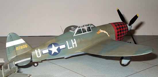 ds.
Time to 30,000 feet was only 6 minutes, 45 seconds. Now that's an interceptor!
Yet it had a usable range of 1,075 miles. Rather impressive, don't you think?
And, no, this was not a stripped down hotrod. It was fully armed and carried
ballast in the wings equal to 267 rds per gun. The aircraft was flown to a
height of 46,500 feet and was capable of a bit more. Weights were 9663 pounds
empty, 12,400 pounds normal loaded, 16,780 pounds maximum.
ds.
Time to 30,000 feet was only 6 minutes, 45 seconds. Now that's an interceptor!
Yet it had a usable range of 1,075 miles. Rather impressive, don't you think?
And, no, this was not a stripped down hotrod. It was fully armed and carried
ballast in the wings equal to 267 rds per gun. The aircraft was flown to a
height of 46,500 feet and was capable of a bit more. Weights were 9663 pounds
empty, 12,400 pounds normal loaded, 16,780 pounds maximum.
Originally designed to defeat the FW-190 series fighters, the XP-47J certainly would have been a potent adversary. In point of fact, with its critical Mach of .83, it had the potential to chase down Me-262's by utilizing a shallow dive, taking advantage of its superior service ceiling.
Despite this incredible performance, the XP-47J was really nothing more than a technology demonstrator. Meanwhile, the R-2800 C series was installed in another, more ordinary Thunderbolt P-47C. The purpose was to trade a little performance for simplicity of manufacture. The idea being that a minimum of changes were required to the current aircraft for the C series engine. The aircraft that resulted was the production “hot rod” Thunderbolt, the P-47M.
As an aside, apparently during durability testing of the C series R-2800 by Republic, it was decided to find out at what manifold pressure and carburetor temperature detonation could be induced. They ran the engine at extreme boost pressures that produced 3,600 hp! But wait, it gets even more amazing. They ran it at 3,600 hp for 250 hours, without any failure! This, with common 100/130 avgas. No special fuels were used. Granted, the engines were completely worn out, but survived without a single component failure.
The above was all retrieved from the internet, so I cannot prove or disprove any of it. Most of the other references to the “J” are usually just the fact that it broke 500mph in level flight. In any event, everything I have read (and that you have just read here) points to the fact that this was a very capable machine.
| THE KITS |
This ‘Bolt is a Koster
vacuform conversion using the trusty Monogram P-47 Razorback kit. The Monogram
kit in itself still makes into a fine Thunderbolt, even though it is decades
old. Of course if raised panels lines are not your thing, then stay away.
Raised panel lines do not bother me in the least, and not one person has even
looked in my display case and in disgust said “eeeeewwwwww, that one has rai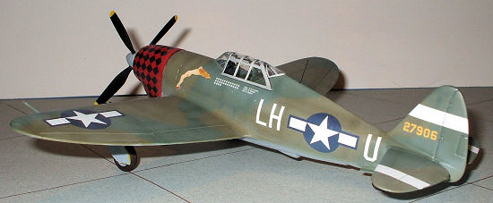 sed
detail!” And as many have pointed out in reviews here, sometimes raised detail
mimics the real thing better. Anyway, my kit was from 1987 (from one of
Monograms dual kit Air Combat Classics boxings that also includes a Do-335) but
I know the kit goes back to the 1970’s somewhere. It is molded in olive drab
plastic. Very crisp detailing, very little flash, and I’ve always loved
Monograms “fabric” detailing…very petite.
sed
detail!” And as many have pointed out in reviews here, sometimes raised detail
mimics the real thing better. Anyway, my kit was from 1987 (from one of
Monograms dual kit Air Combat Classics boxings that also includes a Do-335) but
I know the kit goes back to the 1970’s somewhere. It is molded in olive drab
plastic. Very crisp detailing, very little flash, and I’ve always loved
Monograms “fabric” detailing…very petite.
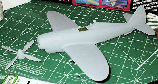
The Koster vacuform conversion has one sheet of white plastic that includes the new fuselage and cowling halves…these replace the kit pieces. Also included are very nice resin bits comprising of the engine cooling fan, supercharger intake, and a new propeller/spinner. The engine cooling fan had a strange spiral of tiny air pockets at the surface; the propeller/spinner had a few tiny air holes on the blades and a prominent seam at the prop line. The propeller would be easy to correct, the fan I wasn’t going to touch…not much of the blemishes would be seen anyway, so why bother? Also in the conversion is one clear vac piece for the cut-down rear canopy area, and a single sheet of instructions. Overall a nice conversion set.
| CONSTRUCTION |
Construction did not, in this case, start with the cockpit. It starts with the vacuformed parts, which need to be removed from the sheet.
However……a slight problem. I had never done a vac kit before and really didn’t have much of a clue. So I went back and found and re-read many of the vac kit reviews here at MM and also acquired some nice vac FAQ’s from several sources. They all point the same way.
Rule
#1: Get a sharp pencil. So having acquired said utensil, I drew a line around
each part on the sheet. I then took one of my larger X-acto knives with a
curved blade and scored on the outside of the pencil mark of each part, trying
to keep the knife at 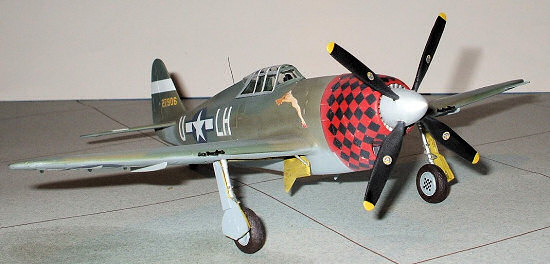 about a 45 degree angle, angled in towards the part.
Rule #2: Snap, don’t cut. No need for the score to go all the way thru, as the next step is to “snap” the parts from the sheet. I tried this first on some of the scrap plastic of the sheet; as I really didn’t want to screw this up on step one. All of the parts did snap cleanly from the sheet.
Next step is to carefully sand down all the parts to eliminate the “waste” plastic that is there. This is the thickness of the backing sheet, well, because it is the backing sheet. Cutting the parts at a 45 degree angle back “into” the parts helps reduce the waste which helps reduce the amount of sand time, and anything that reduces the amount of sanding is a good thing. This is also where the pencil mark comes into play.
Rule #3: The pencil line rules!! Do not forget this. I picked a suitable flat area (a plate of glass is recommended, but my kitchen table was made to work in lieu of that) and taped some sandpaper to it. The idea is to sand until the pencil line just disappears, but no farther. I started with 150 grit, and then moved to 400 as I got closer. I checked the part often, checked the line often, but I think I still managed to sand a little too much on the fuselage halves, for it is a bit leaner than the original kit pieces. Not anything anyone will notice though, just apparent when comparing next to the kit parts.
Once I got the vac pieces sanded down I cut and glued onto each piece small tabs, pieces of Evergreen strip, to act as assembling aids. These worked out very well since the vacuform plastic is much thinner than the injected bits and hence, not much gluing surface. So now I have two fuselage halves and two cowling halves that replace the kit parts and construction continues like a “normal” kit. So lets get to that cockpit………
Hhhmmmm…nothing
major here, the whole cockpit consists of four parts, one of which (cockpit back
plate) you do not use. I painted this assembly and the fuselage interior a
suitable shade of green and popped out the details by dry brushing a bit. I
 painted the seat belts that are molded in the seat but they just didn’t look
right. I did by chance notice a lonely Eduard photo-etch Sutton harness in the
stash. Since none of the Spitfires or Hurricanes in the closet spoke up to
claim it when I asked, I used it here. Now, I know it is not the correct style,
but hey, it still makes it look better. This assembly was then glued into one
side of the fuselage. This is a bit fiddly, as there are no attachment points.
I ended up making support posts from Evergreen rod and glued them to the side of
the cockpit bucket to get it to sit right. When I was satisfied with this I
carefully glued the fuselage halves together. I set this aside to dry and moved
in on the cowling. I glued the two halves together and fitted the resin bits.
The turbocharger intake fit very nicely, but I had to trim the cooling fan to
get it in there. After this was dry I cemented it to the fuselage.
painted the seat belts that are molded in the seat but they just didn’t look
right. I did by chance notice a lonely Eduard photo-etch Sutton harness in the
stash. Since none of the Spitfires or Hurricanes in the closet spoke up to
claim it when I asked, I used it here. Now, I know it is not the correct style,
but hey, it still makes it look better. This assembly was then glued into one
side of the fuselage. This is a bit fiddly, as there are no attachment points.
I ended up making support posts from Evergreen rod and glued them to the side of
the cockpit bucket to get it to sit right. When I was satisfied with this I
carefully glued the fuselage halves together. I set this aside to dry and moved
in on the cowling. I glued the two halves together and fitted the resin bits.
The turbocharger intake fit very nicely, but I had to trim the cooling fan to
get it in there. After this was dry I cemented it to the fuselage.
Next I removed the bomb pylons from the wings, as the J wasn’t going to be burdened buy these. I filled in the resulting holes with scrap vac plastic and then filled and sanded them smooth. The short (outboard) gun barrel then was cut off and the long (inboard) barrel trimmed back to the length of the now-outboard barrel. Confused yet? The J was only to carry six machine guns, the center weapon being the farthest forward. I shouldn’t have even bothered doing this, as I proceeded to break off four of the six remaining over the course of the build. I ended up replacing the gun barrels with brass tubing. Once all this was done I attached the wings to the fuselage. The fit here was surprising good, but definitely not as “positive” as the injected plastic. I made up some jigs to get the dihedral correct and let it sit to dry. I then added the tail planes and over the next few days I puttied and sanded down the seams till all looked well.
I then diverted my attention to the resin propeller and spinner. As I mentioned it was blemished by random air holes and a mold seam on the spinner. I filled all these with CA glue and hit it with a few drops of my super secret accelerator (water…works great and is quite cheap) to cure it. I sanded things down, looked things over, and repeated the process. Once it looked good to me I shot this and the somewhat complete airframe with British Medium Sea Grey (Testors Model master enamels) to act as a primer and as the bottom color, having already somewhat deciding on a paint scheme. Did the “paint, inspect, sand, repeat” cycle a couple times till all was good. Or at least good enough!
On to the paint shed…….
| COLORS & MARKINGS |
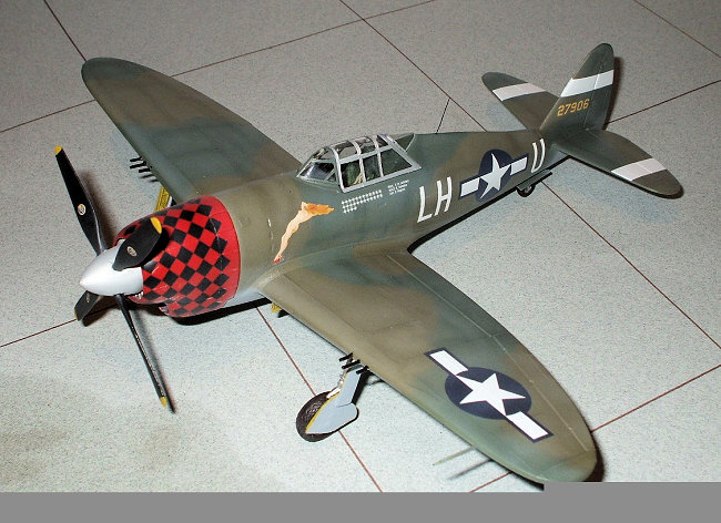
I could have easily just modeled the prototype, but I decided to go with the “Allied ‘46” theme. Allows much more creativity. My first thoughts were that of a London defender in 1946. On starting this project I only knew two things about the final scheme:
1) It was not going to be the normal Olive Drab/Grey.
2) It was not going to be NMF.
 I
perused reference books and the internet for ideas….not sure what I wanted.
What I did find was a profile (from the internet) and a color picture (from one
of my references) of a bird from the 63rd fighter squadron of the 56th
fighter group. It had dark and medium green upper colors over a grey
underside. Aluminum (unpainted?) canopy and a red nose. Hhhhhhmmmmmm….that’ll
work. About the same time I came across an Eagle Strike decal sheet (48-171) of
a Thunderbolt with a yellow and black checkered nose and a lovely nekid lady on
both sides in front of the cockpit. Methinks if I swap the yellow nose for a
red one and if I can get the black checkerboard decal on the new cowl shape,
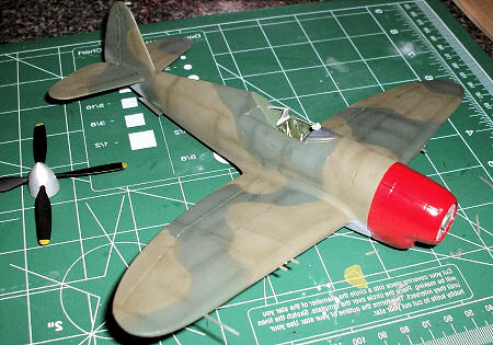
that’ll look pretty cool. So that’s the direction I headed. I sprayed the
cowling with Testors red (little bottle) and then tried deducing the correct
camo colors. I thought US medium green and British dark green looked about
right for the colors, but I was out of the dark green, so substituted
RLM 82 instead, which is very close. After
spraying these two colors and comparing the result to the pictures, it just
didn’t look right. The medium green was, well, too green. Okay, on to plan
“B”. I ended up grabbing some olive drab (go figure!) and tried that. Much
nicer.…to me anyway. So, satisfied with that, I went over the panel lines with
darker shades of each and then sprayed lighter shades of each into the center
area of each panel…trying my best for a multi-hue look. I think it turned out
pretty nice. A couple thin coats of future and she was ready for decals.
I
perused reference books and the internet for ideas….not sure what I wanted.
What I did find was a profile (from the internet) and a color picture (from one
of my references) of a bird from the 63rd fighter squadron of the 56th
fighter group. It had dark and medium green upper colors over a grey
underside. Aluminum (unpainted?) canopy and a red nose. Hhhhhhmmmmmm….that’ll
work. About the same time I came across an Eagle Strike decal sheet (48-171) of
a Thunderbolt with a yellow and black checkered nose and a lovely nekid lady on
both sides in front of the cockpit. Methinks if I swap the yellow nose for a
red one and if I can get the black checkerboard decal on the new cowl shape,
that’ll look pretty cool. So that’s the direction I headed. I sprayed the
cowling with Testors red (little bottle) and then tried deducing the correct
camo colors. I thought US medium green and British dark green looked about
right for the colors, but I was out of the dark green, so substituted
RLM 82 instead, which is very close. After
spraying these two colors and comparing the result to the pictures, it just
didn’t look right. The medium green was, well, too green. Okay, on to plan
“B”. I ended up grabbing some olive drab (go figure!) and tried that. Much
nicer.…to me anyway. So, satisfied with that, I went over the panel lines with
darker shades of each and then sprayed lighter shades of each into the center
area of each panel…trying my best for a multi-hue look. I think it turned out
pretty nice. A couple thin coats of future and she was ready for decals.
My
biggest concern with the decals is whether I would be able to use the diamond
pattern checkerboard on the new cowl shape. I made a paper template the shape
of the decal to test cut and fit to the cowl. Luckily for me, the cut needed
was right at a checker “line”, with the portion wrapping under the engine
trimmed just a bit shorter. Looked like it would work just fine. And it did,
the decals wrapped around and snuggled down fine, though they did resist the
first treatment of Micro-sol. Of course, I did manage to screw something up.
When I merrily sprayed away with the red on the cowl, I covered the whole cowl.
Looking at the decal in place and then at the directions (which, by the way, is
pretty much the exact opposite of how you really should do it) I realized I
should not have painted the cooling flaps, so now the decal looked too short.
Just didn’t look right. But fear not! When I ordered
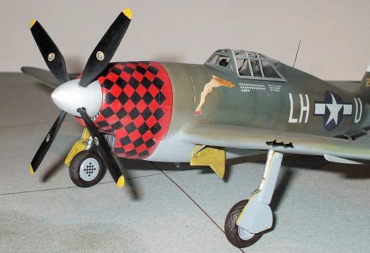 the decals, I ordered two
sets, thinking it might be nice to have the diamond checkerboards in the stash
for future use. Well the future had arrived sooner than expected. I took the
second set of decals and cut one row of diamonds off of it and put it place.
Looked much better. The rest of the decals went on without a hitch. The girlie
art decal is along the lines of the Pyn-Up series in that you put a white
backing decal in place and then apply the very nicely printed artwork on top of
it. As with the Pyn-Up series, you have to trim around the final artwork
portion closely.
the decals, I ordered two
sets, thinking it might be nice to have the diamond checkerboards in the stash
for future use. Well the future had arrived sooner than expected. I took the
second set of decals and cut one row of diamonds off of it and put it place.
Looked much better. The rest of the decals went on without a hitch. The girlie
art decal is along the lines of the Pyn-Up series in that you put a white
backing decal in place and then apply the very nicely printed artwork on top of
it. As with the Pyn-Up series, you have to trim around the final artwork
portion closely.
At this stage I added a gun sight. No, not the kits’ gun sight…par for the course for me in that I had already lost it. Many of us know of the dreaded carpet monster that devours small pieces that fall off the workbench never to be seen again. Well, I have a hunch that my place is also inhabited by gun sight gnomes, who remove these parts from boxes at night. How else to explain the loss….it can’t be my fault!!! So I scavenged an extra one from an upcoming project. I then tried to modify the original headrest to a new shape as per the conversion instructions. I tossed it in the trash after sufficiently mangling it. So I got out the evergreen sheet and made a new one. I added the already painted canopy and rear glass (Metalizer Non-buffing aluminum) and sprayed a mixture of Testors flat acrylic and future to try to get a semi-gloss look. I’m sure they would have kept the hotrod polished for a bit more speed!
| FINAL CONSTRUCTION |
Time
to put on all the final bits. This was the point in the build that…..drum roll
please…..I dropped the model.
 Right off the table and onto the floor. Super
cringe…didn’t want to look. Not after all this work. I opened my eyes and
looked down to see the damage. One airplane. No pieces. No way!?! I picked
it up off the floor and amazingly nothing had broken off. Must be my superior
building techniques….yeah right!! J
I figure luck was with me and it hit just right or…the flexibility of the vac
plastic actually helped out…maybe it bounced rather than broke. However it
happened, I was one happy camper. To prevent a reoccurrence, I quickly cordoned
off the work bench with warning signs and caution tape to keep all things with a
pulse at a safe distance (well, except myself of course, who was the biggest
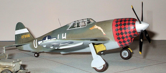
threat of all!) and proceeded to attach landing gear, wheels, and the like. I
attached that great big spinner and added a whip antenna and she was done.
Right off the table and onto the floor. Super
cringe…didn’t want to look. Not after all this work. I opened my eyes and
looked down to see the damage. One airplane. No pieces. No way!?! I picked
it up off the floor and amazingly nothing had broken off. Must be my superior
building techniques….yeah right!! J
I figure luck was with me and it hit just right or…the flexibility of the vac
plastic actually helped out…maybe it bounced rather than broke. However it
happened, I was one happy camper. To prevent a reoccurrence, I quickly cordoned
off the work bench with warning signs and caution tape to keep all things with a
pulse at a safe distance (well, except myself of course, who was the biggest
threat of all!) and proceeded to attach landing gear, wheels, and the like. I
attached that great big spinner and added a whip antenna and she was done.
| CONCLUSIONS |
I really enjoyed this build. I was a bit apprehensive about the vacuform parts, but that wasn’t bad at all. Just adds a little more time to the build, and hey, I’m not in a hurry anyway. I’ve always liked the look of the P-47J and this conversion kit gave me the chance to build it and learn a bunch of new stuff along the way. As for screw-ups there are my usual many. Remember when I said I think I sanded the vac parts just a little too much? Well, the canopy and clear rear window seemed just a tad wide when I put them on. Not by much, mind you, not anything anyone will notice, but that confirmed my suspicions. Remember…the pencil line rules!
| REFERENCES |
The internet
http://home.att.net/~jbaugher1/p47_9.html
http://www.geocities.com/Pentagon/Quarters/9485/P-47M.html
The Mighty Eight in Color (ISBN 0-933424-57-4)
October 2007
Thanks to me and my fondness for anything different from the norm for this one.
Copyright ModelingMadness.com. All rights reserved. No reproduction in part or in whole without express permission from the editor.
If you would like your product reviewed fairly and quickly, please contact the editor or see other details in the Note to Contributors.