| KIT: | Pavla 1/72 P-43 Lancer |
| KIT #: | 72061 |
| PRICE: | Over 20 dollars |
| DECALS: | Four options |
| REVIEWER: | Joel Hamm |
| NOTES: | Short run multi-media kit |
| HISTORY |
Pavla and its associated Czech companies have dedicated themselves to the proposition that modeling is more than Me 109’s. For upwards of a dozen years they have brought us a steadily improving stream of oddities, underdogs, also-rans, and in-betweens. The Lancer’s shape makes obvious is membership the last category, as a development step between the Seversky P-35 and the Republic (which Seversky in Sept. ‘39 became) P-47 Thunderjug. Technical history more detailed than anyone cares to read is available on 17 Google pages; but one quip bears paraphrasing – that these 3 aircraft were a gift of the Russians; as their designers, Alexander de Seversky and Alexander de Kartveli were émigrés fleeing the Bolshevik government.
| THE KIT |
 This is a re-issue of one
marketed just a few years ago, with resin goodies newly added. It is comprised
of one sprue of blemish-free engraved grey injected plastic parts, a bag of
superbly rendered resin, two sets of vacu-sucked canopies and side windows, a
PEB (Photo-Etched Brass) fret holding an instrument panel and exhaust ducts
(latter used in only one version), and a photo-film of instrument faces to go
with the PEB panel. The only medium not represented in this kit is raisin-walnut
flavored Philadelphia brand whipped light cream cheese. Decals are top-notch
markings for two US, one British, and one Chinese aircraft. Instructions are the
usual 16 page booklet of pictures that range from exceptionally clear to utterly
ambiguous.
This is a re-issue of one
marketed just a few years ago, with resin goodies newly added. It is comprised
of one sprue of blemish-free engraved grey injected plastic parts, a bag of
superbly rendered resin, two sets of vacu-sucked canopies and side windows, a
PEB (Photo-Etched Brass) fret holding an instrument panel and exhaust ducts
(latter used in only one version), and a photo-film of instrument faces to go
with the PEB panel. The only medium not represented in this kit is raisin-walnut
flavored Philadelphia brand whipped light cream cheese. Decals are top-notch
markings for two US, one British, and one Chinese aircraft. Instructions are the
usual 16 page booklet of pictures that range from exceptionally clear to utterly
ambiguous.
Pavla’s resin pouring
deserves further mention, particularly the engines. The Pratt & Whitneys are
furnished as separate cylinder banks (front made by Pratt, back is from
Whitney), each of which is molded with - now catch this – integral but
free-standing push rod tubes. I.e. there is no webbing attaching them to the
cylinders. The accompanying photos may not show this, but blue sky can be seen,
and the Four Winds can 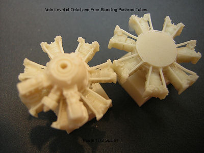 circulate
between the cylinders and the tubes. Don’t ask me how this was done. It seems
physically impossible, as the rubber mold would have to fill that space, then
like the Red Sea part to allow withdrawal of these micro-filaments.
circulate
between the cylinders and the tubes. Don’t ask me how this was done. It seems
physically impossible, as the rubber mold would have to fill that space, then
like the Red Sea part to allow withdrawal of these micro-filaments.
After admiring the engine for a while under high magnification, I would have been only half surprised to split it open and find pistons, valves, and a crank. If these former Eastern Bloc technicians are capable of such machinations, then thanksgiving is due that we are no longer ideological adversaries. And if that is the kind of detail made possible by poured resin, then I may have to change my main modeling medium.
The resin seat is another work of art/magic. It is molded with clearly distinguishable belts, buckles, elevating frame, and even the belt anchoring structure behind the backrest. All the cockpit furnishings are somehow shrunk down from full size. Peek at it under magnification and the handgrip on the stick looks like a handgrip. The gun sight looks like a gun sight. I went a bit nuts and replaced the molded-in reflector screen with one cut from thin clear sheet, but when the windscreen goes on it’s quite visible to the naked eye.
| CONSTRUCTION |
 First the cockpit walls were
busied up with Evergreen strip stringers. After the halves were mated,
additional bogus-ness was added from below in the form of a brass trim wheel and
radio face on the right, and a scratched power quadrant on the left, to which I
later added wire throttle and prop levers, topped with balls of appropriately
painted Elmer’s Glue. Couldn’t quite squeeze in a mixture control, but that
lever was usually located elsewhere. The rear bulkhead needed trimming, and a
forward bulkhead had to be cut to make a sticking place for the instrument
panel. Seat and stick were left out to facilitate masking, which is better done
with chunks of foam rubber than tissue paper.
First the cockpit walls were
busied up with Evergreen strip stringers. After the halves were mated,
additional bogus-ness was added from below in the form of a brass trim wheel and
radio face on the right, and a scratched power quadrant on the left, to which I
later added wire throttle and prop levers, topped with balls of appropriately
painted Elmer’s Glue. Couldn’t quite squeeze in a mixture control, but that
lever was usually located elsewhere. The rear bulkhead needed trimming, and a
forward bulkhead had to be cut to make a sticking place for the instrument
panel. Seat and stick were left out to facilitate masking, which is better done
with chunks of foam rubber than tissue paper.
I must wax repetitive about the level of detail devoted to these kits – far greater than can be appreciated in 1/72 scale. Held up to the light, the photo-film reveals specific instrument faces, such as the needle-ball, and gyro-horizon (as it was then called). Best way to mate this to the brass panel is with Future or other clear coat, though care must be taken during the pre-paint wash not to dissolve the bond with strong cleaners.
Parts are provided to box in the main gear wells. Before attaching the spar faces I prettied them up by drilling lightening holes. That’s lightENing, as in weight reduction. Aviation, model and real, is demanding of enunciation. A passenger once asked me why parts of the airplane were punctured by big holes. I explained that they were lightening holes. She blanched and her knees started to give. “You mean, like - to let the lightning go through?” Also – never refer to an uncommanded roll as “a wing falling off”. The phrase is a sure chaser of students and riders.
 The addition seemed probable of
a longitudinal panel between the wells, also presumably properly pierced. There
are living only a very few people familiar with the belly innards of a P-43
Lancer. None will ever glimpse the inside of my model, and get a chance to
criticize this imagined arrangement of structural members. If these partitions
existed, they were doubtlessly perforated, if not to save weight, then certainly
to let the lightning go through.
The addition seemed probable of
a longitudinal panel between the wells, also presumably properly pierced. There
are living only a very few people familiar with the belly innards of a P-43
Lancer. None will ever glimpse the inside of my model, and get a chance to
criticize this imagined arrangement of structural members. If these partitions
existed, they were doubtlessly perforated, if not to save weight, then certainly
to let the lightning go through.
Of less certain authenticity were the corrugated panels provided for the well roofs. Wheel apertures are generally stuffed with pipes, tanks, wires, and assorted actuators, a set of generic representations of which would make a saleable aftermarket item. In any event, the entire assembly had to be ground down to fit within the height of the sealed wing.
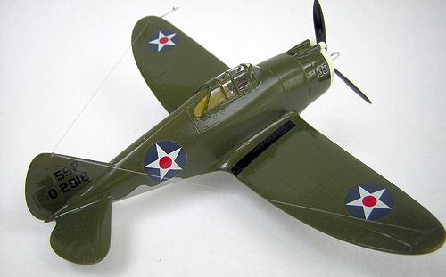
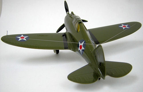
Which wing did not, by a long shot, fit “seamlessly” to the fuselage. To close the 2+mm gaps at each root, the fuselage bottom had to be fattened with sprue stretcher rods. A gaping mismatch where the trailing edge “beavertail” joins the rear fillets also demanded muscling into place, followed by lavish filling and filing. Fortunately, that area, in addition to being on the underside, is occupied by the exhaust stack and turbo supercharger. Unfortunately, after the fillers and affixatives had dried and shrunk, the poor little pursuit ended up with noticeably more dihedral than ever intended by Mr. Seversky, Mr. Kartveli, Mr. Pavla, or me.
The vertical fin is a separate part and before attachment should be drilled at its leading edge tip to anchor the antenna wire. . All 3 tailplanes have to be joined without benefit of locating tabs or pins, but the instructions include head-on drawings verifying that everything should be at right angles.
| COLORS & MARKINGS |
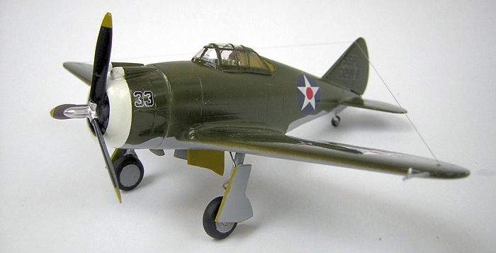
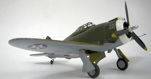
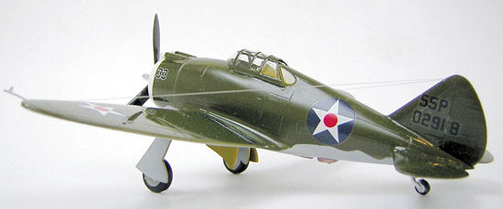
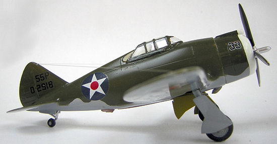
With a yellow cowl ring and tricolor rudder, the natural metal version would have been the most colorful; however all the filing and finagling at the wing juncture demanded a finish that would hide, not accentuate, surface flaws. Besides which, all the other members of my Early Air Corps Fighter Collection wear OD/NG, so that foolish consistency continued being the hobgoblin of this small mind.
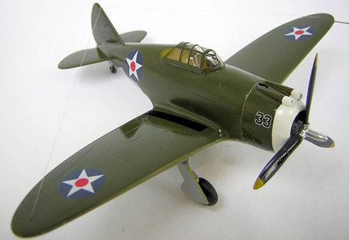 Since the white cowl
ring was the first area to be sprayed, I continued shooting rearward and primed
the whole airframe gloss white, which verified the wisdom of hiding everything
under a thick coat of enamel. A few dribbles of black added to the mix turned it
into Neutral Gray for the underside. Olive Drab for the up-sides was concocted
out of gloss green, orange, and brown. Glossing flats for decals only to be
re-flatted is just inviting trouble.
Since the white cowl
ring was the first area to be sprayed, I continued shooting rearward and primed
the whole airframe gloss white, which verified the wisdom of hiding everything
under a thick coat of enamel. A few dribbles of black added to the mix turned it
into Neutral Gray for the underside. Olive Drab for the up-sides was concocted
out of gloss green, orange, and brown. Glossing flats for decals only to be
re-flatted is just inviting trouble.
Some of the painting instructions were questionable, such as zinc chromate on the wheel hubs. The box art confirmed the hunch that these were more likely gray. The diagrams also show the belly exhaust stack painted gray to match the belly. It may have been, but it would not have long remained that way.
The raised canopy framing precluded my usual method of embedding strips of Pactra Trim Tape in a heavy coat of Future, so transparencies were sprayed, after masking panes with aluminum foil stuck on with Uhu stick glue. The Reynolds wrap can be tightly pressed into each panel and leaves a sharp edge when cut with a razor blade. The stick-um stuff is water washable so residue is never a problem. And, of course, the combination is cheaper and easier to obtain than Bare-Metal Foil.
Whosoever printed the decals did it right. The markings are thin, properly colored, without film surrounds on the insignia, but are finicky about slipping and sliding and must be floated into position. They settled down just fine without setting fluids. A test shot with Micro-Set on an unused Chinese roundel showed no increase in snuggle factor, so all were left that way. Incidentally, the left and right vertical fin markings are not identical, so check the marking guide to get them right.
Future sealed everything, diluted approx 3:1 with 70% alcohol, to slow the drying rate in the Summer Dog Day swelter and form a thinner, less glossy coat.
| FINAL CONSTRUCTION |
 The rear quarter windows are
provided as vacu-forms; but it’s much simpler to cut them from flat stock. I
re-used the tape that had been cut to shape to mask the window wells, stuck it
on a piece of acetate, then cut then sanded around it, beveling slightly.
Getting the panes to sit in the openings was - well – a pain – and would have
been easier if I had deepened the wells with a scraper before beginning
assembly. Future didn’t do a good enough job of holding them, so I switched to
epoxy. Me, CA glue, and transparencies have never made a happy threesome.
The rear quarter windows are
provided as vacu-forms; but it’s much simpler to cut them from flat stock. I
re-used the tape that had been cut to shape to mask the window wells, stuck it
on a piece of acetate, then cut then sanded around it, beveling slightly.
Getting the panes to sit in the openings was - well – a pain – and would have
been easier if I had deepened the wells with a scraper before beginning
assembly. Future didn’t do a good enough job of holding them, so I switched to
epoxy. Me, CA glue, and transparencies have never made a happy threesome.
The vacanopy (vac – canopy) is thick, but not as clear as deserved by all the inner furnishings. Open cockpits in 1/72 scale never looked right. Add-in detail, at least the scratch built stuff, is by necessity an oversize representation (my power levers are bowling balls atop tree trunks) made plausible only by the acetate’s optical distortion. In any event, it fit with minimal fiddling.
The Main gear struts are ludicrously long and must be trimmed at both the oleo and fork ends by at least 3 mm. The latter cut means attaching new axles and deepening the wheel cutouts. I’m not whining or whimpering, mind you, just wondering how they could have gotten the buckles on the seat belts so right and the length of the landing legs so wrong.
 In typical Pavla
fashion, the injected prop blades must be mated to the resin hub. To make an
alignment jig I fished a 3 bladed out of the spares box, poked its shaft through
a sheet of styrofoam, and marked where the tips extended. Getting an equal and
appropriate pitch was another matter. The pins molded on the hub are too fat to
be drilled into the blade bases. I sanded them off, drilled matching holes in
the blades and bosses, then assembled all with wire pins.
In typical Pavla
fashion, the injected prop blades must be mated to the resin hub. To make an
alignment jig I fished a 3 bladed out of the spares box, poked its shaft through
a sheet of styrofoam, and marked where the tips extended. Getting an equal and
appropriate pitch was another matter. The pins molded on the hub are too fat to
be drilled into the blade bases. I sanded them off, drilled matching holes in
the blades and bosses, then assembled all with wire pins.
Anyone building the Chinese version is on his own as to configuration and placement of the PEB exhaust ports, or whatever they are, on the aft fuselage. Neither the instructions nor the box art offer sufficient clue.
Mating the engine / cowling assembly to the fuselage didn’t make a happy endig to the project. The firewall just confused things so I discarded it. A soupscon of white glue caulked the gaps where the cowl flaps met the fuselage.
| CONCLUSIONS |
If Pavla brings the quality of their injected parts up to the level of their resin pourings, they’ll have the Italmygawans truly worried.
October 2006
If you would like your product reviewed fairly and quickly by a site that has over 325,000 visitors a month, please contact me or see other details in the Note to Contributors.