
AZ Model 1/48 Firefly TT.1
| KIT #: | AZ 4864 |
| PRICE: | $38.00 |
| DECALS: | Four options |
| REVIEWER: | Torben Plesberg |
| NOTES: | Short run kit |
| HISTORY |
The Fairey Firefly was a shipboard fighting plane built for the Royal Navy during the second half of the second world war. The Firefly would replace an earlier Fairey design: the Fulmar. The new aircraft was specified for a top speed of 300 knots and with a crew of two, a pilot and a navigator. The Firefly was designed around the new Rolls Royce Griffon engine.
The first prototype took to the air for the first time on 22 December 1941, but even before this event the admiralty had ordered 200 aircraft “off the drawing board”. The Firefly was heavily armed as a fighter with four 20 mm Hispano cannon mounted in pairs in the wings. The prototype was 40 mph. faster than the Fulmar, even if it was some 4000 lbs. heavier.
 The first Fireflies were
delivered to the Royal Navy squadrons in March 1943, but the type was not
operational until a year later. The Firefly served with distinction for the
rest of the war, mainly in the Far East and Pacific Theatres, but also
against the Tirpitz in Norway. After the war the Firefly remained in front
line service with the Royal Navy until it was replaced by another Fairey
design: the Gannet.
The first Fireflies were
delivered to the Royal Navy squadrons in March 1943, but the type was not
operational until a year later. The Firefly served with distinction for the
rest of the war, mainly in the Far East and Pacific Theatres, but also
against the Tirpitz in Norway. After the war the Firefly remained in front
line service with the Royal Navy until it was replaced by another Fairey
design: the Gannet.
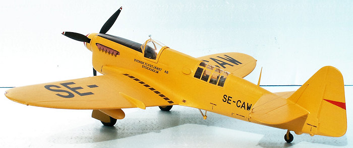
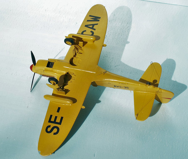
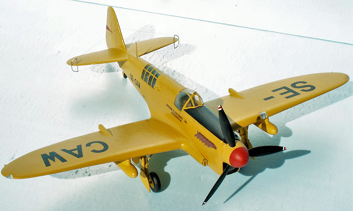
After the second world war there were large surplus stocks, and Fireflies were supplied to the air arms of Canada, Australia, Denmark. Ethiopia, the Netherlands, India and Thailand. Some Fireflies were converted to target tugs to replace the Miles Martinet TT in British service. The towing gear of the Martinet was simply built into the Fireflies, and some of the Firefly TT 1 were sold to Denmark (6), India (10) and a Swedish civil company – Svensk Flygtjänst AB Stockholm (16). The Danish Fireflies were acquired in 1951 and they served until 1959, when the three surviving planes were sold to Svensk Flygtjänst.
In the mid-fifties I often watched a yellow plane towing a red target, when visiting my grandparents in their cottage at the coast some 25 kilometers south of Copenhagen. One km to the north there was a small fort with AA guns, and I could often hear the noise of the shooting. On one occasion the target suddenly fell down into the sea. The gunners had hit the towing wire. I ran all the way to the small harbor close to the fort, and arrived in time to watch a boat bringing the target in. There were a lot of holes in the target. What a pity I did not possess a camera at that time!
 Some 8 years later – in
1963 – I visited Bulltofta Airport at Malmö in Sweden. I was invited by Bo-Göran
Lundkvist, who was an employee of the airline “Transair Sweden”, and he gave
me access to watch some very interesting aircraft, and this time I had my
camera with me. There was a Firefly TT 1, two Gloster Meteor TT Mk 20 and
two Douglas Skyraiders, former AEW Mk 1 of the Royal Navy – all five
aircraft belonging to Svensk Flygtjänst. The Firefly had the registration
SE-CAW, the last of the 16 aircraft acquired from the Royal Navy surplus
stocks and modified for TT 1 by Fairey Aviation Company. This aircraft was
in the end presented to the Danish Aviation Museum, and will be restored as
Firefly 630 of the Royal Danish Air Force. It will probably be ready for
exhibition about 2020.
Some 8 years later – in
1963 – I visited Bulltofta Airport at Malmö in Sweden. I was invited by Bo-Göran
Lundkvist, who was an employee of the airline “Transair Sweden”, and he gave
me access to watch some very interesting aircraft, and this time I had my
camera with me. There was a Firefly TT 1, two Gloster Meteor TT Mk 20 and
two Douglas Skyraiders, former AEW Mk 1 of the Royal Navy – all five
aircraft belonging to Svensk Flygtjänst. The Firefly had the registration
SE-CAW, the last of the 16 aircraft acquired from the Royal Navy surplus
stocks and modified for TT 1 by Fairey Aviation Company. This aircraft was
in the end presented to the Danish Aviation Museum, and will be restored as
Firefly 630 of the Royal Danish Air Force. It will probably be ready for
exhibition about 2020.
Here is a small joke about the Firefly in Danish service: During an aircraft recognition exercise in the fifties, a bloke from northern Jutland reported from his watch tower to the HQ: “fire fly”. He was asked to report what type of planes they were, but he just repeated: “fire fly”. The bloke was not familiar with the English language, and he simply pronounced the name from the aircraft recognition book – Firefly – in Danish, meaning four planes!” Fire” = four and “fly”= plane(s). “Fly” is short for flyvemaskine = plane or aircraft. The Danish word for firefly is “ildflue”.
| THE KIT |
Inside the box there are two large sprues of medium grey plastic, a transparent sprue, two small sheets of photo-etched parts, one of these covering the TT 1 variant, and some bars with resin parts covering the interior of the crew stations, super detailed wheel wells, some very nice exhaust pipes, the winch arm and alternative four spoke main wheels for the undercarriage. The interior parts allow a very detailed cockpit and winch operator station. However, when the canopy parts are glued in place, you can only see very little of the interior details. It might be a waste of effort to build up a complete interior!
 The photo –etched parts are by
nature only two-dimensional, and this means that some of the parts are useless –
especially all the parts for the TT 1 version!
The photo –etched parts are by
nature only two-dimensional, and this means that some of the parts are useless –
especially all the parts for the TT 1 version!
It may be false to announce on the box that it contains a kit for the Firefly TT 1. The kit is actually for a Firefly FR 1, complete with four Hispano cannons and carrier hook. If you choose this version, you will have to find a suitable decal sheet on the aftermarket. However, there is a nice decal sheet for the TT 1 version, a photo-etched sheet with the specific TT 1 parts, a single resin bar with the winch arm and 4 spoke main wheels, and step 14, 15 and 21 of the instructions showing how to place the parts for the TT 1.
As it is a short run kit, you can’t expect that all parts fit perfectly together. The fit between the fuselage and wings is rather bad. This is of course only a matter of filling and sanding. The recessed panel lines are in some places filled out with excessive plastic. This means that you must check all the panel lines and recreate the lines with a knife, a scriber or a small file wherever they are absent.
The instructions consists of eight A5 pages containing 21 steps covering both the FR 1 and the TT 1. I found the instructions poor, since I was often wondering exactly how the parts should be put together. I spend a long time to figure out how to interpret the instructions. However, in the end the built was a success – in spite of the instructions. They were especially bad concerning the TT 1 modification, and even wrong. Without my own photos of the SE-CAW I would have been rather lost.
| CONSTRUCTION |
In this review it is not necessary to repeat, what the instructions tell to do. I will explain in detail what I did to make the Swedish Firefly TT 1 SE-CAW. I will offer a few pieces of advice to make the assembly easier or better.
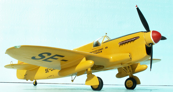
 The spinner is too long and too
bulbous. To deal with this problem I carefully glued the spinner to a rod of
Ureol, which in the lathe had been turned down to a gauge 0.5 mm bigger than the
gauge of the spinner. If there is this small difference, it is easier to make
the spinner center exactly for the lathe. Now it was possible to reduce the
length of the spinner by 2 mm and make it less bulbous – a bit more pointed.
However, be careful not to remove too much material from the spinner, unless you
have filled the top inside with Plastic Padding. The gauge of the spinner is 18
mm and the length should be about 15 mm. The finished spinner can be easily
removed from the Ureol rod with a razor saw.
The spinner is too long and too
bulbous. To deal with this problem I carefully glued the spinner to a rod of
Ureol, which in the lathe had been turned down to a gauge 0.5 mm bigger than the
gauge of the spinner. If there is this small difference, it is easier to make
the spinner center exactly for the lathe. Now it was possible to reduce the
length of the spinner by 2 mm and make it less bulbous – a bit more pointed.
However, be careful not to remove too much material from the spinner, unless you
have filled the top inside with Plastic Padding. The gauge of the spinner is 18
mm and the length should be about 15 mm. The finished spinner can be easily
removed from the Ureol rod with a razor saw.
I wanted the propeller to turn properly and when the prop blades and the bottom disc were glued in place, it was possible to fix it in a three yaws chuck and drill the center hole for a brass propeller shaft gauge 2.5 mm.
The hole in the assembled fuselage should be drilled with a 3.5 mm drill to allow a brass tube with a 2.5 mm hole as bearing for the propeller shaft. The length of the brass tube was 2 cm.
The propeller tips are wrong: they should not be pointed, but oblique cut, longest in the direction of the rotation. The length of the prop blades seems to be right. My turning propeller has not been locked with a disc inside the fuselage, but as the shaft is 2.5 cm long, the risk of falling off is only very small. It is just a question of not letting the nose of the model face downward, when handling the model.
I also wanted to make the landing light, as I have a photo taken head-on and clearly showing the landing light in the front of the port wing. The “glass” should be 5 x 6 mm. With a 5 mm cutter it was an easy job to make the exact opening for the glass in the port wing. A piece of 5 mm acryl was then cut a little bit larger than the opening, and the glass could be filed and sanded exactly to match the wing profile. To simulate the light I punched a 3 mm disc from a piece of vapor sealing tape, which is silver glossy, and fastened it on the wing behind the glass. It was not necessary to glue the glass, the fit was tight enough.
The position lights in the wing tips should also be on the model. I cut away the small pieces which were marked for the these lights. The new transparent pieces were cut in a piece of 2 mm acryl. They are very difficult to handle because of their small size, but with a forceps with rifled yaws used as a vice it was possible and even get the wing profile right using a very fine needle file. The “lights” were made by drilling 2 mm deep holes with a 0.5 mm drill an filling the holes with transparent green and red paint – HB no 1321 (red) and HB no 1325 (green). It looks quite realistic.
 Now some advice concerning
wings and tail planes. As the Firefly TT 1 was unarmed, all traces of the four
guns must be removed, the four stubs in front of the wings and the four bulbs on
the top of the wings. As to the tail planes it is a good idea to secure them to
the fuselage by means of a small brass tube. The gauge should not exceed 2 mm,
and the drilling must be very precise, if you want the tail planes to be placed
correctly, both as seen from above and as seen from behind. I had to drill one
of the holes in the fuselage once more with a 2.5 mm drill to obtain absolute
symmetry. I glued the tail planes in place before I glued the fuselage halves
together.
Now some advice concerning
wings and tail planes. As the Firefly TT 1 was unarmed, all traces of the four
guns must be removed, the four stubs in front of the wings and the four bulbs on
the top of the wings. As to the tail planes it is a good idea to secure them to
the fuselage by means of a small brass tube. The gauge should not exceed 2 mm,
and the drilling must be very precise, if you want the tail planes to be placed
correctly, both as seen from above and as seen from behind. I had to drill one
of the holes in the fuselage once more with a 2.5 mm drill to obtain absolute
symmetry. I glued the tail planes in place before I glued the fuselage halves
together.
Before the fuselage is glued together, the nice exhausts must be glued in place, and the radiator in the right half. The assembled crew station for the winch operator was also glued in place in the right half. A third part to be placed now is the bottom part where the arrester hook is half buried. This part must be filled and sanded a couple of times to eliminate the grooves for the arrester hook, since the TT is not carrier borne..
The crew station for the pilot may be placed after the assembly of the fuselage – through the big opening in the bottom where the assembled wings fit. It is possible to detail the crew stations rather much, but when the canopies are glued in place, you can only see a trifle of all your effort. I would call it waste of time to detail the crew stations. I only used the instrument panel from the photo etched parts, as this can be seen.
The Swedish Fireflies had a pair of wing tanks, which might have been 45 gallons drop tanks during the war service of the aircraft. They were made of 8.3 mm gauge acryl rods, 52 mm long and rounded in both ends. The pylons are 37 x 6 x 6 mm and were made of Ureol. The concave curving to conform with the tanks was milled, an easy job. More difficult was to make the pylons conform with the wing profile, but white glue is very well suited to deal with small cracks, and no sanding afterwards is necessary.
The assembly of the wing to the fuselage is simple, but the fit is very bad. There are cracks exceeding 1,5 mm on either side of the fuselage. But it is simply a matter of filling and sanding a couple of times, and the cracks are invisible.
And now it is time for the undercarriage. The legs fit into some holes in the wheel wells. But the holes are not deep enough to secure a steady position of the legs. You must be very careful, when gluing the legs in place, and secure the correct angle as seen from the side and from the front. If the legs were 2 mm longer, it would have been easier to drill the holes 2 mm deeper, and then the position of the legs would have been right at once. The position of the wheel doors is not entirely correct, but there is no help in the instructions. A photo of an actual Firefly taken from the side will show the exact position of the doors. However, since the wing tanks cover the doors, the flaw is not obvious, and I decided not to do anything about it. The wheels should be the resin ones, because they have four spokes, besides is the quality better. The plastic five spoke wheels are for the wartime Firefly FR 1.
 The tail
wheel is OK, but the leg for it is not. I am sure that the idea of gluing two
very thin pins to the wheel center is a bad one. The risk of a break down of the
tail wheel is big. Therefore I soldered my own leg of brass wire, and this will
not break down, even after a hard landing. The leg was fastened in a 4.5 mm
gauge acryl rod, which was milled flat on two opposite sides, to make the rod
fit into the opening for the tail wheel. The rod was long enough to be glued to
the inside top of the fuselage. It is important to be careful with the length,
since it should conform with the hole for the tail wheel on the bottom of the
fuselage.
The tail
wheel is OK, but the leg for it is not. I am sure that the idea of gluing two
very thin pins to the wheel center is a bad one. The risk of a break down of the
tail wheel is big. Therefore I soldered my own leg of brass wire, and this will
not break down, even after a hard landing. The leg was fastened in a 4.5 mm
gauge acryl rod, which was milled flat on two opposite sides, to make the rod
fit into the opening for the tail wheel. The rod was long enough to be glued to
the inside top of the fuselage. It is important to be careful with the length,
since it should conform with the hole for the tail wheel on the bottom of the
fuselage.
And now for the canopy parts. The windscreen is OK and can be applied without problems. The hood is also OK, but it cannot be applied without some modification. The rear end of the hood leaves a gap of about 1.5 mm to the fuselage. This flaw can be corrected by making two wedges tapering from zero to 1.5 mm. When these are glued in place on the upper edge of the fuselage sides, the gap is gone. The hood , however seem to be too thick in the bottom frames and in the rear frame. This can be corrected by filing the edges oblique from the inner side. This must be done with the outmost care. The job is finished when a good fit is obtained, and hopefully without damaging the fine clear bubble hood.
The green house is too long by two frames for the TT 1 model. The two- frame piece is cut with a razor saw blade in the middle of the second framing from the front. The two- frame piece is then glued to the fuselage, and filled and sanded until conform with the fuselage. Now the two bulbs for the wire winch can be glued in place, P 29 and P 30. The mill arm P 31 is not applied, because the Swedish Fireflies got a hydraulic winch system in the mid-fifties.
An important part of the wire system is the wire deflectors to protect the tail planes and rudder against damage from the tug wire. The photo-etched parts PPE 7 are unusable, because they are far too thin and delicate, and it is impossible to fasten any wire to them without destroying the whole thing. That is why I made two new frames of 0.5 mm nickel silver wire, they look like the frame of a hacksaw or a jig saw. The height of a frame is one sixth the height of the rudder, about 8 mm.
 In this
connection I will mention that the drawing of the Firefly TT 1 by Björn
Karlström is incorrect in this matter, p. 31 “Flygplansritningar 7”. Both the
size and shape of the frames are wrong on this drawing. On p. 33 in the same
book there is a fine color photo of Firefly SE-BRL taken from behind. This photo
shows clearly the size and the shape of the frame.
In this
connection I will mention that the drawing of the Firefly TT 1 by Björn
Karlström is incorrect in this matter, p. 31 “Flygplansritningar 7”. Both the
size and shape of the frames are wrong on this drawing. On p. 33 in the same
book there is a fine color photo of Firefly SE-BRL taken from behind. This photo
shows clearly the size and the shape of the frame.
Since the frames are not made of circular tubing, I hammered the wire to be more flat. The dimension of the wire ended up being 0.6 x 0.3 mm, very suitable for the frames. It is obvious that the 0.3 mm side must face the direction of flight to minimize air resistance. I made a jig out of wood with the exact inner profile of the frames, and then it was easy to bend the wire around this and get two identical frames. The ends of the wire must be a little above the middle of the longest side of the frames. It is necessary to open the frames to put them into the 0.6 mm holes drilled in the tail plane wingtips, and close the frame again with a pair of pliers. The ends of the wire is supposed to be hidden in the holes.
Next problem was to place the reject wire from the frames and to the fin, and to the second bulb behind the tail wheel - the smaller one. I first used a 0.3 mm gauge wire, but it was far too thick and clumsy. Then I tried some fishing line about 0.2 mm gauge. However, the super glue could not fasten this material to the frames. In my stocks I have an assortment box with a lot of spools of different sewing thread. In this box I found a spool with an 0.1 mm black “thread”. This was exactly what I needed to make the reject wire correct to the scale. It was rather easy to fix the wires with knots and secure them with super glue. If you look at the model from a distance of 40-50 cm, it is difficult to see that there is a wire.
The Swedish Fireflies had a flat rod antenna on the top of the fuselage a little ahead of the tail plane. This antenna was cut in 0.3 mm brass plate and the edges were sanded smooth. The antenna should be 12 mm long.
The last item was the wire guide on the underside of the fuselage just behind the wing. It is the “thing” made by photo etched parts PPE 3 and PPE 5, step 14 in the instructions. However, this arrangement does not correspond to what I can see on my photos. I scratch built the thing and made it look, as the photos showed me. The purpose of the thing is to control the tug wire in the air during target towing.
| COLORS & MARKINGS |
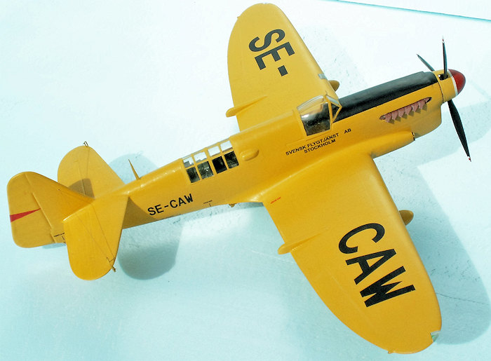
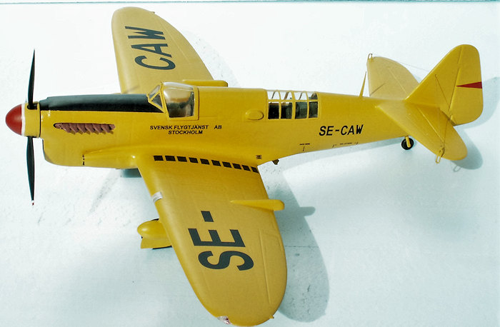
The color scheme is very simple: interior of crew stations - interior green HB 78, and everything else trainer yellow, HB 24. There are the following exceptions from the over all trainer yellow:
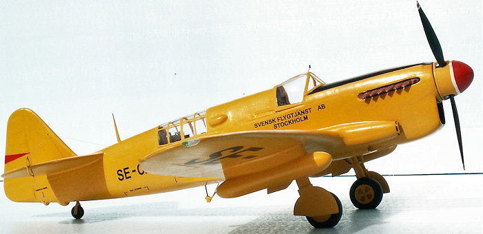 The anti
reflex area in front of the cockpit and to the spinner is flat black – HB
33. The same color for the tires and the propeller blades. The walkway on
the port wing, ten flat black squares about 6 x 4 mm stretching from a
little ahead of the cockpit and to the trailing edge of the wing.
The anti
reflex area in front of the cockpit and to the spinner is flat black – HB
33. The same color for the tires and the propeller blades. The walkway on
the port wing, ten flat black squares about 6 x 4 mm stretching from a
little ahead of the cockpit and to the trailing edge of the wing.
The radiator is gun metal – HB 53 - both seen from the front and from the bottom.
Propeller tips are white HB 22 with a red stripe in the middle – HB 19. In the turning direction there is a black stripe along the edge of the propeller blade .
The outer half of the spinner is scarlet red – HB 60, and so is the “arrow” on the rudder.
There is a 2 mm white ring between the red and the yellow of the spinner
To make the trainer yellow look best possible, it is a good idea first to prime the airframe with white – HB 22 a couple of times.
All places to be decaled got Gloss Cote from HB, and after decaling the whole airframe got HB Satin Cote. The decals are first class quality. Only the FLYGTJANST needed a pair of full stops above the A to spell the word correct in Swedish: FLYGTJÄNST. I did not apply all of the stencils. The following were put on the model: 4a NO STEP, 6a HAND/FOOT, 1a tail lifting, 9a trestle here, and 10a jacking point.
The 1.5 mm white ring of the spinner between the yellow and the red color was made as a decal of a white sheet of decal paper. The gauge was about 3.5 cm, but only 52 mm was needed for the full circle.
| CONCLUSIONS |
As a short run kit the Fairey Firefly TT 1 is by far not a super kit. However, with some skills it is possible to produce a reasonable model. The kit is recommended, because the only alternative would be a completely scratch built model. Producing such a model would take a very long time, and probably not be worth the effort.
Remember – the kit is actually a Firefly FR 1, but with a different sheet of decals to make it a TT 1. Besides there is an extra small sheet of photo etched parts for the winch system, and an extra resin bar with bulbs and arm for the mill and two 4 spoke wheels for after war use.
A kit definitely not for beginners. The kit was released in the beginning of April 2013, and has long been sold out. I bought my kit in Sweden in the middle of July 2014. I had been waiting for this kit for about 50 years, so I was very happy to get it, and apparently also lucky!
| REFERENCES |
Wikipedia: The Fairey Firefly.
Björn Karlström: Flygplansritningar 7, p. 30-33. Allt om Hobby, Stockholm. ISBN 91-85496-68-5
Photos of SE-CAW taken at Bulltofta Airport, August 1963.
April 2016
Copyright ModelingMadness.com