Hasegawa 1/48 Typhoon IB
|
KIT # |
9059 (JT 59) |
|
PRICE: |
$31.98 |
|
DECALS: |
Two aircraft |
|
REVIEW & |
Paul Mahoney |
|
NOTES: |
Ultracast seat and wheels used` |
|
HISTORY |
There are plenty of experts on the Typhoon out there, so I'll keep the history
brief.
Hawker's Typhoon was in the design phase almost before the Hurricane was
rolling off the production lines. It was designed around the 2000+ h.p. Napier
Sabre Engine that, although powerful, was initially plagued with problems.
The urgencies of War caused the early Typhoons to be rushed into production
without the normal testing that might have been done. The result was near
disaster. Of the initial 142 Typhoons delivered to the RAF, 135 suffered serious
accidents without any enemy action being involved!!
Engines were catching fire upon start. Carbon monoxide was leaking into the
cockpit. And the tail section would break off during high speed maneuvering.
Despite all these problems, in 1942 the Typhoon was the only a/c the RAF had
that was able to catch the 'Jabo' FW190s that were making regular sorties over
England.
Eventually most problems were addressed - an 'in the field' addition of
so-called 'fish-plates' were added to the fuselage/tail unit joint for added
strength. This solved that problem and became part of production. Bulkheads
were replaced in an attempt to eliminate the carbon monoxide seepage, but pilots
still learned to go immediately to oxygen before starting the engine just in
case. Maintenance and quality control solved a lot of the other issues
associated with the Napier engine. In time, newer, more powerful models of that
engine were produced that were less trouble prone and drove Typhoons, and
eventually Tempests, even faster.
While the Typhoons were the fastest thing around in the RAF at ground level,
their performance dropped radically with altitude. As the 'Jabo' threat against
England dissipated, the role with which Typhoons became most closely associated
emerged - that of ground support. Typhoons could carry large payloads of bombs
and rockets. This armament, augmented by four 20 mm cannon, was devastating to
almost anything on the ground. 'Cab ranks' of Typhoons would circle just behind
the lines, ready to be called in by forward air controllers at a moment's
notice.
Although quickly phased out of service after the War, the Typhoon remained the
standard by which future ground attack aircraft of the RAF were to be judged for
years to come.
|
THE KIT |
Hasegawa's kit of the Typhoon comes in many variations. As has become their
habit of late, they have stretched the molds to allow the same basic kit to make
many variants. As most who have heard of this kit now know, this means there
are some cumbersome fuselage inserts around the cockpit area to allow the basic
molds to produce either the Car Door or Bubbletop canopy version.
The cockpit and wheel wells are well detailed. Engraved detail is standard
Hasegawa - that is to say, it is superb. Detail all around looks crisp, and
with the exception of the fuselage inserts, looks to be a fall together type of
kit.
I built this kit more or less out of the box, with the exception of adding in
some of the Ultracast resin bit and some minor cockpit detailing..
Kit measurements appear to be fairly accurate, using the figures in the Profile Publication listed in my references.
|
CONSTRUCTION |
I began my construction with the cockpit. Hasegawa did a great job in here,
providing the tubular framework, as well as several panels, switches, etc. One
glaring exception to this great detail is the very plain seat that is provided.
Ultracast has come to the rescue with a very crisply molded resin seat
(including harnesses). I used their mid/late war version, which may have the
wrong harness type for this particular Typhoon, but I was asked to review these
bits, and I had the Car Door model on hand!
I have found conflicting data regarding the colors of Typhoon cockpits. Some sources say they had all-black interiors, while others say interior green. I went with interior green. Unless I have an exact photo of the aircraft I am modeling, I will go with a 'best efforts' approach.
In addition to the seat, I added several small details to the cockpit. Some wire running down the length of the control stick, and a few other knobs and switches. While I didn't intend to 'go to town' on an already decent cockpit, I did try and add any missing prominent details. The compass mounted directly under the instrument panel was noticeably absent. I used one of the small round molding tabs that are in the center of the bomb rings as the base for my compass. (so I guess Hasegawa DID provide the compass, just not where one my expect to find it!). I replaced the reflector portion of the gunsight with a small rectangle of clear acetate from the collar stiffener of a new shirt.
One area of concern to me was the massive radiator. The main air intake for the engine runs right through the center of this. After gluing the two radiator halves in the kit together, I could see clear through this intake hole. That didn't seem right! A brief moment of panic ensued, which resulted in a post on the Hyperscale board (where there are some extremely helpful people, and somewhere out there, at least someone will be able to answer your query). Immediately it was pointed out to me that the rest of the intake trunk is molded into the lower wing. Guess that will teach me to keep test-fitting prior to panicking! In addition, I picked up all kinds of helpful Typhoon and Napier engine tidbits from the board. A great help!
Crisis averted, the construction continued. The next challenge was the cockpit surround inserts. There are two inserts - one for each half. The left insert is one piece, while the right-hand side is split to allow for an open door. I decided the best approach was to glue each insert to it's respective fuselage half, and then join the completed halves. Note that the insert/fuselage seam does not fall on a panel line. After carefully gluing the inserts to each half, it became apparent that: a) the existing panel lines do not line up between insert and fuselage (not far off, but not perfect alignment), and b) when joining the fuselage, the main halves are a near perfect seam, but the inserts have a noticeable gap between them. I glued the fuselage halves together, and let everything set up for 24 hours or so. I did discover that if I squeezed the top of the fuselage (where the inserts are) together, I could eliminate most of the gap between them without too much distortion. I did so, and things started to work out. I would recommend following this sequence, rather than gluing the inserts together first. The inserts are a little smaller than the overall fuselage, and this seems to be the only method that does not result in a step between the fuselage and the insert. Next came the challenge of eliminating the insert/fuselage join. A few applications of putty, and lots of sanding did the trick. I rescribed the panel lines that were lost during this process, and managed to get a passable effect where the crossover from fuselage to insert occurs.
 The wings went together smoothly (don't forget to drill out the holes for the
bomb racks if you are using them). The main fuselage/upper wing seam needed a
tiny bit of putty, but nothing difficult. As usual for Hasegawa, the rear
wing/fuselage join was less than perfect. This was really the only other
trouble spot besides the inserts.
The wings went together smoothly (don't forget to drill out the holes for the
bomb racks if you are using them). The main fuselage/upper wing seam needed a
tiny bit of putty, but nothing difficult. As usual for Hasegawa, the rear
wing/fuselage join was less than perfect. This was really the only other
trouble spot besides the inserts.
I used the new (to me) technique described on Aircraft Resource Center to putty in the tiny gaps in the upper wing/fuselage seam. This has got to be one of the best 'new' things I have read about recently - and fairly simple to do. Lay masking tape down on either side of the seam, leaving a very small bit of plastic on either side of the seam exposed. Now apply putty into the seam using a toothpick, your finger, or whatever you normally use. Remove the tape. While the putty is drying, take a rag soaked in nail polish remover and wipe along the seam. The putty stays in the seam, and is removed from the surrounding area. No sanding necessary! I have found this only works well in natural panel lines or areas that need to be filled in., It doesn't work well in areas (such as the rear wing/fuselage) that need to be smoothed by putty. These spots require a build-up of putty, and this process removes too much. The great thing about this process is that no surface detail is marred, and no sanding is necessary! Great for those tight areas that are hard to sand. Thank you Aircraft Resource Center!! While I'm on the subject of the wings, the cannon fairings that are molded in the upper and lower wings fit together a little less than perfectly. I did not apply glue to this area until I was done with most of the construction. I then used an alligator clip to hold each of the halves together and applied liquid glue. Since they do not line up that well, great care must be taken when sanding the joint to ensure the cross section remains circular.
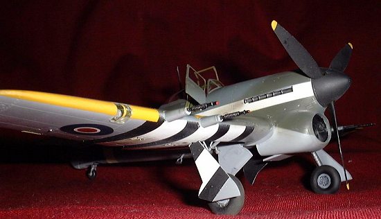
I attached the canopy prior to painting, and masked it off using Parafilm for the curved surfaces and Scotch (green plaid box) tape on the rest, exposing the frames by cutting around them with a new Xacto blade. Since I was planning on posing the door and canopy in the open position, I used the kit's 'closed' door to help mask the cockpit. The rest of the exposed cockpit and the radiator were masked off with damp tissue paper, sealed in with liquid mask. I also attached the landing gear doors in the 'up' position prior to painting using liquid mask. This way I could line up the underside colors on the door correctly.
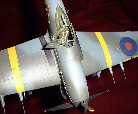
After all painting was done, the rest of the assembly went very quickly. I added lengths of wire to the main struts to represent hydraulic lines, then attached the struts to the landing gear covers. Hasegawa has done a good job of replicating some nice details in the landing gear mechanism, and in the gear bays as well. A good paint job and some washes will bring out this detail beautifully. One small complaint, and it is really a general one as Hasegawa is not the only one that does this: The one-piece tail wheel and strut leaves a bit to be desired. Invariably when tail wheels are molded like this, the demarcation line between the tire and the strut is not very crisp, which makes it difficult to paint realistically. It can be done, but with all the other crisp details of modern kits, I am continually disappointed in the tail wheels. The molding of the strut itself is quite nice, and accurate, but molding the tire integrally with the rest of the strut detracts from this. With after market manufacturers doing such a great job on main wheels, I would like to see them issue some tail wheels and struts.
 Speaking of main wheels, I used the Ultracast Typhoon wheels on this kit.
These are an absolute gem. Very crisp resin moldings. Nice details,
including the stem. They have a slight bulge and flat spot, which looks
about right to me. Mounting them would have been a bit easier if the axles
on the landing gear were a little longer, but that is really not that much of a
problem.
Speaking of main wheels, I used the Ultracast Typhoon wheels on this kit.
These are an absolute gem. Very crisp resin moldings. Nice details,
including the stem. They have a slight bulge and flat spot, which looks
about right to me. Mounting them would have been a bit easier if the axles
on the landing gear were a little longer, but that is really not that much of a
problem.
Once the gear was completed, I added all the other small bits to the underside of the aircraft. Note that the antenna blade on the underside of the a/c was not present in all Ib's. Once again there are no absolutes, so check your photos. I found more photos of 'car doors' without this antenna than with it. While I'm on the subject of the antenna, the main antenna mast does NOT have a wire running to the tail. There is, however, a small loop of wire that can clearly be seen in photos running from the antenna mast inside the canopy to the canopy frame (and further down to the radio equipment I would imagine). I forgot to add this until after the canopy was glued down, so spent quite some time trying to wiggle stretched sprue through the hole for the antenna mast. After several attempts I was able to pull it off.
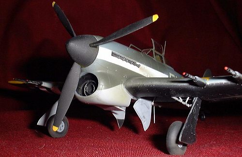
I left the bomb pylons off, as this was a pure fighter. In addition to the fairings covering the cannon, Hasegawa provides you with 2 styles of unfaired cannon barrels, although no mention of this is made in the instructions. Nice to have these little undeclared add-ons. I used the unfaired cannon barrels with the longer springs, and purposely did not drill holes in the tips. Several photos I have seen show caps on the ends of these guns to prevent dirt from entering the barrels. Since this aircraft was going to be modeled as one on a training exercise, it seemed reasonable to assume these caps would be in place. I painted the ends of the barrels red to simulate these caps. I did hollow out the exhaust pipes, which turned out to be quite time-consuming. I started by putting a small hole in each pipe with the tip of an Xacto, then used a pin vise to drill the hole a little larger and deeper, then finished again with the Xacto in order to make an oval opening to match the pipe shape. By the way the seam that runs down the middle of the exhaust pipes is supposed to be there - a molding seam on the real item. Unfortunately, it looks like the molding process forced Hasegawa to have some sprue tabs that are attached to the pipes right along the seam lines. Cutting the tabs off while keeping the integrity of the seams is a bit tricky. After they were cleaned up and hollowed out, I painted them by hand using Testors Metalizer Burnt Iron over a base of flat black.
|
CAMO & MARKINGS |
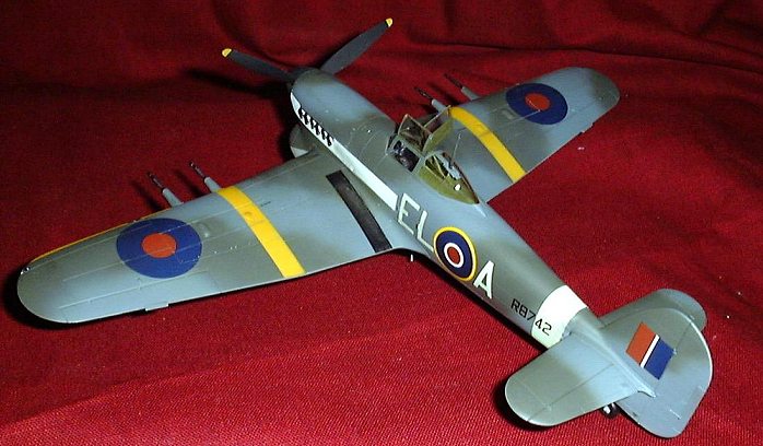
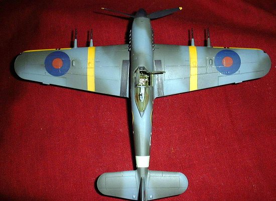
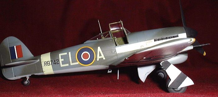
My Typhoon as been painted and marked to represent an aircraft of No.181 Squadron during Exercise "Spartan" in March of 1943.
After all I had been reading about the various schemes to help identify the Typhoon as a 'friendly' a/c (see the website mentioned in my references), I decided I had to paint my model to reflect one of these. Aeromaster's Typhoons in the Sky, Pt. X had a scheme that met the requirements. My a/c had the undersurfaces of the port wing painted black, the black/white id stripes on the starboard underwing (note these are different than DDay stripes - these are 12" black and alternating 18" white, as opposed to the DDay stripes which were of equal size), and the yellow bands on top of both wings. If this wasn't enough to help the a/c stand out a bit, this particular plane also had large white panels on either side of the fuselage as it was participating in Exercise Spartan. These panels were used to designate 'enemy' airplanes during the exercise. Interesting markings, and a bit of a painting challenge to boot.
 I used Model Master enamels for all colors. Standard British Dark
Green/Ocean Grey topsides, Medium Sea Grey underneath. I masked and painted the
black and white stripes, as well as the yellow bands and the Sky-colored
fuselage band. All these are provided by decals either in the kit or on the
Aeromaster sheet, but I much prefer to paint these markings on.
I used Model Master enamels for all colors. Standard British Dark
Green/Ocean Grey topsides, Medium Sea Grey underneath. I masked and painted the
black and white stripes, as well as the yellow bands and the Sky-colored
fuselage band. All these are provided by decals either in the kit or on the
Aeromaster sheet, but I much prefer to paint these markings on.
I know there seems to be an ongoing debate about the sharpness of upper camouflage color delineations on RAF aircraft, so thought I would go through photos myself and see what I come up with. Some say mats were used for painting RAF aircraft at the factories, while others insist there were schematics that were followed by laborers spraying the machines freehand. In looking at photos I saw some Typhoons that had very sharp camouflage lines, while other photos showed me very clearly that there were soft edges between colors. I think it is highly likely that mats were used in some instances, but not in all. The upper/lower camouflage lines seemed to be sharply divided on all aircraft. So, unless you have a photo of the exact a/c you are modeling, I think you can make your own judgment call when it comes to how to delineate the upper colors. I went with the soft edges as I like the look better.
After all painting was done, and several rounds of touchups occurred, I coated the model with Testors Gloss (out of the spray can, as I am still unable to master coverage properly using Future). I used several coats to ensure there would be no silvering of the decals. The Aeromaster decals went on smoothly, as expected. I did use the small amount of stenciling that was included on the Hasegawa sheet, and these too went on very smoothly. After all decals had been applied I brushed some Micro Sol on all of them and let things sit for a day or so. This allowed the decals time to settle in to all the panel lines. There were a few complicated bumps that I was concerned about, but in the end all the decals went down beautifully. Two coats of Testors Dullcoat blended everything in nicely.
I did some chipping and general wear and tear using Testors aluminum. Photos show a decent amount of wear on wing panels more than any other part of these a/c. I used a variety of black, grey, and brown pastels to represent light exhaust staining, panel lines, and various other smudges. I also used some brown pastels to dirty up the tires a bit.
|
CONCLUSIONS |
An enjoyable kit to build. I can't say the kit falls together perfectly, but it
is decent.
Problem areas: 1) lousy fit of the cockpit surround inserts, and 2) underwing/fuselage joint difficult to properly align.
Positives: Very good out of box cockpit detail, beautiful scribing, good
attention to overall detail.
I would recommend this kit to anyone but first time builders (due to the
fuselage insert problems).
Kit provided courtesy of my wallet - Seat and Wheels kindly provided by Ultracast via Scott Van Aken.
|
REFERENCES |
Mason, Francis K., 'The Hawker Typhoon,' in Aircraft in Profile
Bound Volume 4, Doubleday, 1970
Philpott, Bryan, RAF Fighter Units Europe 1942-45 (Aircam/Airwar
10), Osprey Publishing, 1978
Pearson, Bob, 'Painting Up a Storm: Marking Practices of the Hawker
Typhoon' (great website for all markings info on the Typhoon!)
http://members.nbci.com/profileart/quarter2/typhoons-1.htm
Thomas, Chris, Typhoon and Tempest Aces of World War 2 (Osprey
Aircraft of the Aces #27), Osprey Publishing, 1999
If you would like your product reviewed fairly and quickly, please contact me or see other details in the Note to Contributors.