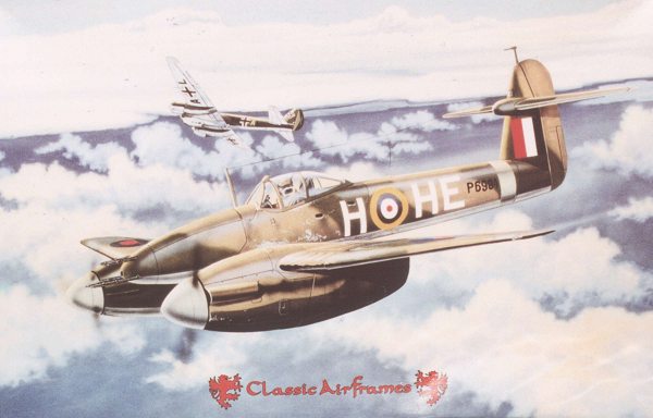
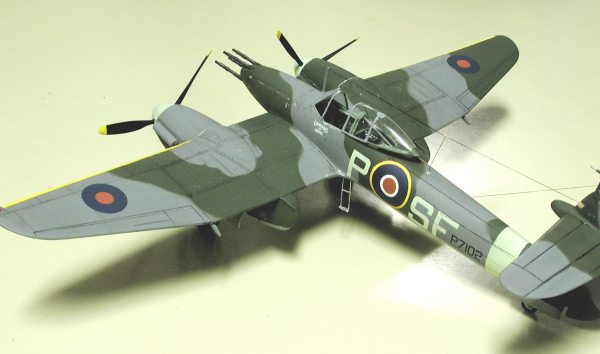
Classic Airframes 1/48 Westland Whirlwind
|
KIT # |
415 |
|
PRICE: |
$39.95 |
|
DECALS: |
Two aircraft: 137 and 263 Sq RAF |
|
REVIEW & |
Grenville Davies |
|
NOTES: |
Multi-media kit` |
|
HISTORY |
The Westland Whirlwind began life as a design to meet the British Air Ministry’s 1935 specification for a fast attack fighter armed with four cannons. It suffered from numerous teething problems and these led to it not reaching service until 1940. The aircraft was the first British fighter to carry four cannons and with the ability to carry a bomb load was eventually moved into ground support. Two squadrons were equipped with the Whirlwind, No. 263 and No. 137.
It was an aircraft that failed to endure despite its highly successful nature. Now this may seem to be a contradiction but the reality is that this beautiful twin-engine, single seat fighter fell foul of delivery problems with its Peregrine power plants coming at a time in the war when things were desperate for machinery parts. It also came at a time when the Spitfire and Hurricane were managing to defend the realm, just. It also came into being about the same time as another twin-engine fighter aircraft, the legendary Mosquito (which nearly suffered the same fate through incredibly bad judgment). The latter had the distinct advantage of being powered by Rolls Royce Merlins, which were easier to obtain. The company chose not to continue making the Peregrine engine and as the Whirlwind was built around this engine, with a redesign too difficult to contemplate, the aircraft production was stopped.
This little aircraft had some endearing qualities to those that flew it, the least of which was its phenomenal speed and handling at relatively low altitudes. The aircraft was used as ground support, which continued until the introduction of the Typhoon, which eventually resulted in the Whirlwind becoming obsolete, along with the fact that its power plant was no longer being produced! This took place towards the end of 1943. Up until that time the Whirlwind shone as a ground attack aircraft, one that could match the performance of any of the then current single seat fighters at low altitudes. To those that first saw the Whirlwind in action came the phrase "Crikey". It was a term that defined the superb speed and handling of this twin-engined fighter with a range of over 1,300 km and a top speed of 580 km/hr (360 mph).
As the Hurricane and Spitfire were gradually more heavily armed with cannons and the Beaufighter started to fill the heavy fighter role, the interest in the Whirlwind began to disappear. By the time the last aircraft had been produced a total of 116 examples had been completed. The aircraft slid into obscurity and yet is fondly remembered by all who flew the Whirlwind.
|
THE KIT |
The kit is multi-media with resin, injection, photo-etch and white metal parts included, along with a vacu-formed canopy. The injection plastic is a light grey with some flash but little in the way of sink marks. There are some ejection pin marks but for the most part these are hidden from view and are easily removed. The resin parts are well moulded and the detail is very crisp.
No locating pins are present for the various halves of the fuselage and wings. This makes it necessary to put tabs inside the fuselage to help locate the halves. Care must be taken when aligning the wings to ensure that there is minimal overlap and subsequent sanding.
The instruction sheet is clear although it could do with some explicit instructions for locating items such as the cockpit sidewalls. Colours are marked for each item and a choice is given for the undercarriage bays. Where the various bits and pieces of this multi media kit are required the instructions are clearly marked.
The decal sheet has markings for two aircraft, one from No. 137 Sqn. and the other from No. 263 Sqn., the decals being crisp and thin with good colour and register.
|
CONSTRUCTION |
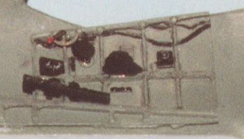
The Cockpit
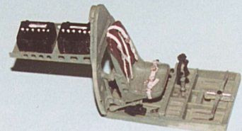 The cockpit
is made up entirely of resin and is very detailed with a large percentage of the
resin parts being located in this area. The resin casting is superb and requires
little work to start assembly. The cockpit floor, sidewalls and instrument panel
are all separate with the seat being mounted on a rear bulkhead. The rear shelf
behind the cockpit bulkhead is made out of photo etch and has two resin pieces
located on top. This is attached at the top cross brace of the rear bulkhead and
needed a bit of fiddling to get it to sit correctly. Don’t forget to attach the
resin fuselage strengtheners behind the bulkhead before closing the fuselage
halves, I did and it was too late once the fuselage halves were joined.
The cockpit
is made up entirely of resin and is very detailed with a large percentage of the
resin parts being located in this area. The resin casting is superb and requires
little work to start assembly. The cockpit floor, sidewalls and instrument panel
are all separate with the seat being mounted on a rear bulkhead. The rear shelf
behind the cockpit bulkhead is made out of photo etch and has two resin pieces
located on top. This is attached at the top cross brace of the rear bulkhead and
needed a bit of fiddling to get it to sit correctly. Don’t forget to attach the
resin fuselage strengtheners behind the bulkhead before closing the fuselage
halves, I did and it was too late once the fuselage halves were joined.
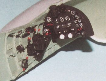 Most of
the cockpit parts were sprayed with Model Master, RAF Interior Green. The
instrument panel was painted Semigloss Black and the instrument dials were
picked out in white. Various throttle levers and switches were painted red or
yellow depending on their function. Once everything had been painted a light dry
brush with silver was done to highlight high wear areas.
Most of
the cockpit parts were sprayed with Model Master, RAF Interior Green. The
instrument panel was painted Semigloss Black and the instrument dials were
picked out in white. Various throttle levers and switches were painted red or
yellow depending on their function. Once everything had been painted a light dry
brush with silver was done to highlight high wear areas.
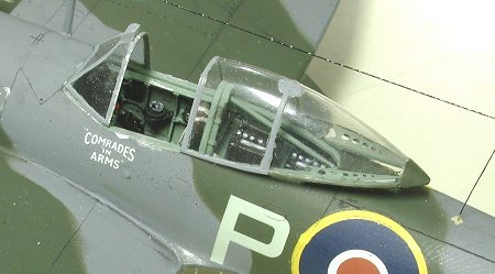
Care needs to be taken when placing the subassemblies into the fuselage, as there are no alignment marks for the sidewalls. I ended up loosely tacking one of the sidewalls into position and then attaching the instrument panel as a guide for its final location. I also needed to sand the top part of the instrument panel to get it to fit inside the front part of the fuselage. The part in my kit was just slightly larger than it should have been so test fit it first and then sand the amount for your piece. I found that it was easier to leave off the gunsight until the front windshield of the canopy was fitted as it invariably was knocked off during the fuselage joining.
The final part of the cockpit prior to gluing on the rear canopy was to add a strengthening rod. In the kit this is presented as a resin part. I chose to replace the kit part with an old broken drill bit of the approximate dimension. It looks more real as the resin part seemed a little flimsy and, given its attachment to the resin sheet, would end up flat on one side.
The cockpit canopy is presented as a vacuform part and is duplicated, the manufacturer seemingly knowing how clumsy some of us tend to be during construction. It requires an extremely sharp or new blade to cut it from the surrounding sheet and caution should be exercised. I chose to split the canopy to better represent the finely detailed cockpit interior. I also chose to paint the internal frame with RAF Interior Green and the outer frame to match the camouflage. I added the small mirror found on top of the forward canopy, by using some plastic card and shaping to match my photo references. The mirror surface was simulated using Gunze Sangyo Gloss Aluminium metalizer that can be buffed, once dry, to a high sheen.
The Fuselage and Wings
 Once the fuselage had dried I connected the lower central
wing portions and added the radiators on the inboard side of each of the engine
cowls. These radiators are painted Semigloss black and are photo etch. When
attaching the upper wing halves I found that they are slightly too tall and had
to bend them towards the trailing edge to allow the wing surfaces to join. It
was necessary to sand the inside of the radiator inlet and carefully clean and
test fit the upper wing surface before gluing. In my kit one side of the lower
wing had buckled and needed some gentle persuasion to mate to its upper partner.
I did think of using special tool part A (namely the hammer), but
opted for the more subtle approach of swearing and bending to the limit of the
plastic’s elasticity – stress testing, if you will! It would be preferable to
try some gentle heating prior to attaching the lower wing, for those of you
attempting this kit if you encounter the same problem. The outer lower portion
of the wing is presented as a separate piece and has a pronounced dihedral when
dry. My kit also had a pronounced gap between the two lower wing surfaces that
required a little filling with gap filling cyanoacrylate, followed (and not too
long afterwards) by some judicious sanding.
Once the fuselage had dried I connected the lower central
wing portions and added the radiators on the inboard side of each of the engine
cowls. These radiators are painted Semigloss black and are photo etch. When
attaching the upper wing halves I found that they are slightly too tall and had
to bend them towards the trailing edge to allow the wing surfaces to join. It
was necessary to sand the inside of the radiator inlet and carefully clean and
test fit the upper wing surface before gluing. In my kit one side of the lower
wing had buckled and needed some gentle persuasion to mate to its upper partner.
I did think of using special tool part A (namely the hammer), but
opted for the more subtle approach of swearing and bending to the limit of the
plastic’s elasticity – stress testing, if you will! It would be preferable to
try some gentle heating prior to attaching the lower wing, for those of you
attempting this kit if you encounter the same problem. The outer lower portion
of the wing is presented as a separate piece and has a pronounced dihedral when
dry. My kit also had a pronounced gap between the two lower wing surfaces that
required a little filling with gap filling cyanoacrylate, followed (and not too
long afterwards) by some judicious sanding.
I elected not to open up the unique radiator exhaust flaps on the trailing edge of the wing as was done in a kit review presented in Scale Aviation Modeller International, Volume 5 Issue 10 October 1999 by David Batt. I did find some references that showed the flap-opening mechanism is a piece of metal that acts as a scissor style opener, but elected to pass. I did remove the rudder and tailplane ailerons and repositioned these to give the model a look of some dynamics. This was done with a knife blade and multiple passes along the panel lines until the piece had separated. This does try one’s patience and I have yet to try the twine method, where the twine is pulled back and forth along the panel line. (Footnote: This method has now been tried on my latest build, a Ju-188, and works very well when care is taken!)
The tailplane sits quite high on the tailfin and again care must be taken to ensure that it sits level. My kit example tended to droop to port and required slight sanding of the mating surfaces to get it to sit correctly.
Undercarriage
The undercarriage is presented in two forms of media with the main struts and supports in white metal and the rear unit in plastic. Both the main wheels and the tail wheel are resin. The tyres were painted with Gunze Sangyo Tire Black and the inner hubs were painted with Tamiya XF16, Flat Aluminium. The undercarriage struts are painted in Tamiya XF16, Flat Aluminium with the main struts being painted flat black on the top part. Very thin, black plastic-coated wire was added to simulate brake lines and attached to the inside hub of each main wheel.
The interior of the main and rear wheel wells were painted in Model Master RAF Interior Green and dry brushed and dirtied up.
I was pre-warned about the fit of the white metal struts into
the wheel wells and, after sanding the main strut join I also thinned the two
legs that join onto the wheel well. I used a small file to chamfer the leg until
it was able to fit onto the outside of the two locating brackets on the inner
forward bulkhead of the well. Both legs were attached using cyanoacrylate on the
two forward struts and rear braces. The tail wheel required a small diameter
piece of plastic rod to be inserted into the hub and this was drilled to take
the two pins of the rear wheel strut. It was also necessary to trim the inside
of the arch to allow the wheel to sit correctly. I attached this at an angle
that conformed to the offset rudder using cyanoacrylate. The strut was painted
with Tamiya XF16, Flat Aluminium and the
 oleo was polished to simulate
the chrome. Another interesting note is that the instructions show the struts as
separate pieces for the main and bracing struts. My example had them joined and,
as they would eventually be attached, I decided to leave them that way.
oleo was polished to simulate
the chrome. Another interesting note is that the instructions show the struts as
separate pieces for the main and bracing struts. My example had them joined and,
as they would eventually be attached, I decided to leave them that way.
The doors for both the main wheels and the tail wheel are quite thick so I chose to thin them down before painting with RAF Interior Green. They were both given some strengthening ribs and attached to the aircraft after final painting. I added some pieces of plastic cut into thin strips for attaching the doors to the wheel wells. Firstly I bent the rods and then glued them onto the doors. They were painted to match the interior colours and then attached to the inside of the wheel well with superglue. I had no references to help with the door closing mechanism so these add-ons are basically a hinged arrangement to help put the doors on the model and certainly not an attempt to duplicate the real deal.
|
COLORS & MARKINGS |
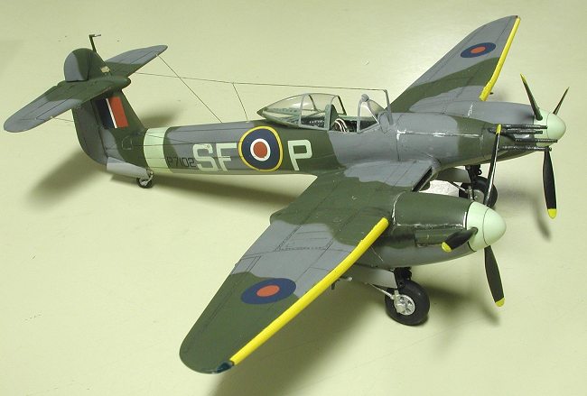
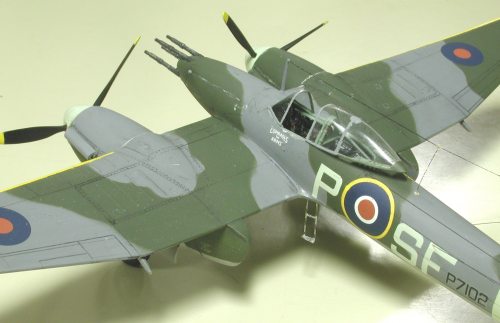
Once I had chosen to use the decals for the No.263 Sqn aircraft the painting became relatively simple, Mid Ocean Grey undersides with Mixed Grey and Dark Green camouflage on the upper surfaces. Simple? Well perhaps not as simple as I would have hoped. The choice of paints here had been made quite a while back when I purchased some PollyScale acrylics and this is the first time I have had the opportunity to test them against my other chosen brands. The Mid Ocean Grey is a standard colour as is the Dark Green, the Mixed Grey, however, is far from standard. This colour was apparently mixed differently every time an airframe was completed. The colour chart provided by Classic Airframes does give the FS number but I elected to have a go myself. I mixed the lower colour with the Dark Ocean Grey from the PollyScale range, after attempting to blend Tamiya Flat Black with the grey. This resulted in an emulsion that was less than satisfactory, so I opted for the same manufacturer paints and no more emulsion. It is also noteworthy that when I used automotive thinners to clean my airbrush that the acrylic PollyScale would not thin, subsequent checking sees that the paint is water based, talk about RTFM! I needed to use the Tamiya Acrylic Thinners to clean up.
Once the two greys had been sprayed, complete with a hard line between the two colours, I proceeded to spray the Dark Green. I have used many different methods of spraying from freehand to using photocopied masks to define the camouflage; in this instance I used a combination of the photocopied masks (after measuring the instruction sheet left, right and top views) and Blu Tack. Once I had mastered the laying on the paper mask onto the Blu Tack the resultant edge was sufficiently subdued.
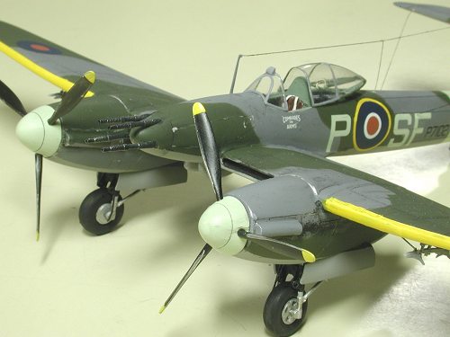
The propeller spinners and the fuselage band were sprayed with PollyScale British Sky after checking between it and the Tamiya Sky to see which better matched the decals. PollyScale is almost a spot on match.
I painted the propeller blades with Tamiya X18, Semi-gloss Black and then masked and hand painted the yellow tips on the blades. I tend to do a fair bit of hand painting on my models, as I can’t be bothered with the fiddling necessary to mask off too much stuff. I have a reasonably steady hand and with the correct temperature can generally avoid unsightly brush marks.
The final painting was the yellow strip on the wing leading edges, outboard of the engines. One word of caution, I used Tamiya Lemon Yellow and it needed a little longer to dry than I had calculated. When I removed the masking tape some of the colour persisted in lifting off. Leave the masking tape on for a couple of hours before handling and it will result in a well-defined line. Mine looked a little ragged and needed touching up and, on one side a re-spray.
 Minor touch ups were necessary to finish the model before
moving onto the decal fixing. Here I used a method I have recently started to
employ, one of polishing the surface where the decal is to go to, flatten the
surface and shine it enough to accept the decals without silvering. It is better
than spraying the entire model with gloss and then having to spray with matte or
semi gloss to do the weathering. In this model the panel lines are very fine and
would certainly have been lost with so much paint. It did not totally eliminate
the silvering and in retrospect I should have used some decal setting solution.
Minor touch ups were necessary to finish the model before
moving onto the decal fixing. Here I used a method I have recently started to
employ, one of polishing the surface where the decal is to go to, flatten the
surface and shine it enough to accept the decals without silvering. It is better
than spraying the entire model with gloss and then having to spray with matte or
semi gloss to do the weathering. In this model the panel lines are very fine and
would certainly have been lost with so much paint. It did not totally eliminate
the silvering and in retrospect I should have used some decal setting solution.
Once the decals were on, the model was given a coat of Gunze Sangyo Flat Clear, which results in a very nice flat surface with a slight sheen. Final attachments of the aerial wires were completed and here I used a technique mentioned in a magazine review, using invisible thread for the aerial and attaching each end with superglue. A flame is then passed close, but not too close, to the loosely fixed filament. As the thread heats up it shrinks into a perfectly taut aerial! Hey Presto! My first attempt saw the thread frizzle as I had gone too close. Give it a try on your next attempt, just wave a match under the thread but don’t get too close or it will make the thread really invisible and you’ll have to start all over again by drilling out those bits left in the frame!
Armament
This little pocket rocket comes with a nasty sting in its nose, in the form of four 20mm cannons. The Whirlwind was also capable of handling a small bomb load of 453kg on under wing racks outboard of the engines.
The cannons were painted in Model Master Gunmetal and dry brushed with silver to bring out the highlights. The ports for these guns were opened out to accept the barrels and they were attached with superglue. In retrospect it would have been easier to open the shaped recesses into which the barrels lie, as this would have allowed a better fit. It was a little difficult to line up the barrels, as there is no positive location mechanism to help, but sheer dint of perspiration won the day – swearing also seemed to help. Perhaps this is common amongst modellers?
|
CONCLUSIONS |
This kit has been described as one that is not a "shake and bake" model and the builder should have experience at handling different types of media before attempting. I can honestly say that with a little patience it can be built into a nice model and most builders, even with a little experience, should enjoy putting it together. First time builders would be better placed if they have had a little experience with resin and photo etch. This is the first truly multi-media kit that I have attempted, although I tend to buy aftermarket accessories for other kits I build, and it went together pretty well.
There was some flash and clean up was necessary on quite a few parts, but on the whole the kit was very well presented. The instruction sheet was clear, although I would have preferred better guidance for fitting some parts, especially the cockpit walls. For the most part things were easy enough to understand and dry test fitting usually saw the part correctly attached.
References for this model were very hard to find and I was lucky to have the review of this kit from SAMI and the Cooper Details vacform kit to help me. I also scoured the web for other reference material and it was very light indeed. I figure that such paucity of reference material means that if anything is really wrong with the model it is less likely to be picked up. No doubt that is fallacious thinking as someone is bound to pull me up over glaring errors. The real problem is that it is a great little kit and I don’t mind if there are errors, it certainly looks like a Whirlwind! A philosophy that I adhere to for most of my building, with rare exceptions!
It is a shame that such an aircraft did not manage to live up to its promise through no fault of the design or the reliability of the airplane. Very few books even mention this aircraft, and those that do refer to it in simple terms. It passed into obscurity just as easily as other well-intentioned aircraft from the period. I would like to thank Classic Airframes for taking a big chance in building the kit and producing a very fine model of an interesting and surprising aircraft that helped in the defence of Old Blighty against the Hun! It is refreshing to find that some companies are prepared to present the "oddball" and unusual of the various aircraft models, rather than playing it safe and offering the run of the mill kits. I look forward to building more from their range. Roll on the Lockheed Hudson!
Acknowledgements
I would like to thank Neil Royes of the Queensland IPMS for his wonderful digital photography of the completed model. Without his efforts the photos would have not been as good, nor shown as much detail – even some of the not so wished for stuff! As a hint look closely at the propeller blades, which now show a little orange peel, and this in the face of my first try at spraying the parts!
|
REFERENCES |
Crikey! Batt, David; Scale Aviation Modelling International, Volume 5 Issue 10, October 1999
Westland Whirlwind Woodgate, Michael; http://www.hyperscale.com/gallery/whirlwindmw_1.html
Westland Whirlwind Plzak, John; Finescale Modeler, May 1999 http://www.finescalemodeler.com/Reviews/May99Reviews/Whirlwind.html
The Westland Whirlwind Pearson, Bob; The Aviation Profiles of Bob Pearson & Chris Banya-Riepl, 1999
http://members.ncbi.com/_XMCM/profileart/quarter2/whirlwinds.html
We Were There Ministry of Defence United Kingdom, http://www.mod.uk/index.php3?page=237
If you would like your product reviewed fairly and quickly by a site that averages thousands of visits a day, please contact me or see other details in the Note to Contributors.