| KIT: | Czech Master Resin 1/72 Spitfire LF.IXE |
| KIT #: | 168 |
| PRICE: | $ |
| DECALS: | 12 options |
| REVIEWER: | Kim Elliott |
| NOTES: | Resin multimedia kit. |
| HISTORY |
The Spitfire IX was essentially a Mk. V, fitted
with a 1500 hp Merlin 60 Series engine and a four bladed airscrew. It was
produced in greater quantities than any other Spitfire variant. This model was a
close performance match to the FW 190 when first introduced to service in 1942.
As originally produced, it was a high altitude interceptor, but was also
produced in low and medium altitude versions. During the MK IX Spitfire
production run the E wing was introduced. This new wing incorporated two Hispano
cannons plus two heavy half inch Browning machine gunss. After the introduction
of Griffon powered Spitfires, the Mk. IXE was adapted to the ground attack rôle.
Post war, Spitfire IXEs were used operationally by both Egyptian and Israeli Air
Forces. One aircraft is maintained in flying condition by the IAF Museum.
| THE KIT |
 An
in-box review was
written by Scott Van Aken on this web-site several months ago, and to this I
will direct the reader for an examination of the contents of the box. Of note is
the many duplicated parts in both resin and photo etch, and decals that allow
one to finish the model as a Yugoslavian version, one of eight Czech versions,
or one of four Israelis. Panel lines are recessed, to a contemporary standard.
In the box, in addition to assembly drawings and a paint/markings guide, is
provided four pages of detail photographs taken of a preserved example of a
Spitfire IXE from a Prague museum. Further, there is a decal stencil placement
guide superimposed on a line drawing of the aircraft. The model manufacturers
have evidently done substantial research. However, comparison was made with
published drawings by D.H. Cooksey and photographs in 'Spitfire - the History'
by Morgan & Shacklady, plus a number of other references. My conclusion: spot-on
1/72 scale, outline shape without fault, and brilliant detailing for the marque.
An
in-box review was
written by Scott Van Aken on this web-site several months ago, and to this I
will direct the reader for an examination of the contents of the box. Of note is
the many duplicated parts in both resin and photo etch, and decals that allow
one to finish the model as a Yugoslavian version, one of eight Czech versions,
or one of four Israelis. Panel lines are recessed, to a contemporary standard.
In the box, in addition to assembly drawings and a paint/markings guide, is
provided four pages of detail photographs taken of a preserved example of a
Spitfire IXE from a Prague museum. Further, there is a decal stencil placement
guide superimposed on a line drawing of the aircraft. The model manufacturers
have evidently done substantial research. However, comparison was made with
published drawings by D.H. Cooksey and photographs in 'Spitfire - the History'
by Morgan & Shacklady, plus a number of other references. My conclusion: spot-on
1/72 scale, outline shape without fault, and brilliant detailing for the marque.
| CONSTRUCTION |
My first act upon opening the
kit was to examine the options. As the example to be modelled was unarmed and
non-operational, gun barrels, bombs, bomb racks, drop tanks, gunsights, and a
few unidentified extra pieces were put aside. Several fine detail parts on the
u/c are duplicated in both resin and P/E. There are three wheel options, two
with P/E hub detail. Two styles of exhausts and two rudders to choose from, one
the early style, the other the pointed one introduced on the IX. Two one-piece
wings, one clipped, the other not. (See image of the unused parts)
Unfortunately, resin is brittle, and despite parts being well packaged in
multiple bags, some parts were broken, some were missing. There are two
different spinner/prop assemblies, one
 being a single part, the other
five components. The single part version had shed a prop blade, and that had
disappeared. At first, I thought the undercarriage legs completely gone, only to
realize that they had been smashed into several pieces. These are cast of a
whitish, presumably stronger, resin than the rest of the mouldings. My first
task, then was to re-assemble the oleos, with cyano glue, and to carve a new
prop blade (resin casting blocks do have their uses!). (Much of this damage can
be attributed to me as after opening the bags to photograph the parts, I put
everything into one zip bag when it was sent on its Perilous Journey through the
Canadian Post. Ed)
being a single part, the other
five components. The single part version had shed a prop blade, and that had
disappeared. At first, I thought the undercarriage legs completely gone, only to
realize that they had been smashed into several pieces. These are cast of a
whitish, presumably stronger, resin than the rest of the mouldings. My first
task, then was to re-assemble the oleos, with cyano glue, and to carve a new
prop blade (resin casting blocks do have their uses!). (Much of this damage can
be attributed to me as after opening the bags to photograph the parts, I put
everything into one zip bag when it was sent on its Perilous Journey through the
Canadian Post. Ed)
Generally, the resin is well formed, without excess moulding flash, and freedom from pinholes. Casting blocks separate easily from the parts. There are some notable exceptions on the wings. In particular, the unused wing had a poor match from the mould halves, which if used, would require a fair bit of filler to preserve the outline accuracy. The standard wing I selected did not suffer from this, but did show notable pinholes on the leading edge. These were filled with Tamiya putty and sanded. The fuselage halves, rudder and stabilizers had minimal flash, cleaned up with fine sandpaper.
A decision was taken at this stage not to remove the blisters over the guns on the wings. Strictly speaking, this should have been done to represent the museum version I was modelling, but I felt that it was a prominent feature on the armed aircraft, and would have been present at some stage of the aircraft's existence.
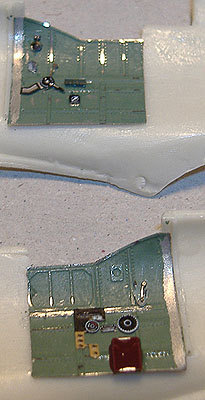 Careful
study of the instructions is necessary before cockpit assembly. 3-D line
drawings, plus photos of the real cockpit, do reveal CMR's intentions, but one
needs to make many choices as to sequence and method. Photo-etch sidewalls match
the inner contoured faces of the fuselage, with minimal trimming. These are
tacked in place with a temporary glue, Microscale's Liquitape, while the resin
seat, bulkheads and seat support are matched to the fuselage half. The
instrument panel, consisting of film, photo-etch and resin, is assem
Careful
study of the instructions is necessary before cockpit assembly. 3-D line
drawings, plus photos of the real cockpit, do reveal CMR's intentions, but one
needs to make many choices as to sequence and method. Photo-etch sidewalls match
the inner contoured faces of the fuselage, with minimal trimming. These are
tacked in place with a temporary glue, Microscale's Liquitape, while the resin
seat, bulkheads and seat support are matched to the fuselage half. The
instrument panel, consisting of film, photo-etch and resin, is assem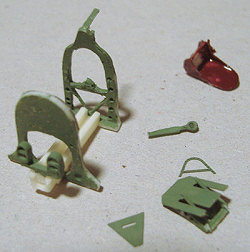 bled
using Humbrol ClearFix, and inserted at this time. Paint, RAF Interior Green or
Bakelite Brown, is applied where necessary. Careful centering of the parts in
the office precedes application of cyano. The cockpit is a miniature wonder, a
state-of-the-art sculpture in resin and pre-painted photo-etch, but will be
virtually invisible once the canopy goes on. Those with more patience and skill
than I could use the provided entrance door and opened canopy to reveal the
interior.
bled
using Humbrol ClearFix, and inserted at this time. Paint, RAF Interior Green or
Bakelite Brown, is applied where necessary. Careful centering of the parts in
the office precedes application of cyano. The cockpit is a miniature wonder, a
state-of-the-art sculpture in resin and pre-painted photo-etch, but will be
virtually invisible once the canopy goes on. Those with more patience and skill
than I could use the provided entrance door and opened canopy to reveal the
interior.
Time should be taken with fuselage halves. Don't sand away all of the fuselage resin "pouring area" without first test fitting first the assembled cockpit and then the wings. One may run the risk of making the fuselage too skinny for good fit otherwise. Back-and-forth trial and error, test-fitting / sanding / test-fitting gives a fit that far exceeds what is experienced with some larger scale multi-media kits. Don't neglect some micro sanding within the root notch area of the wing. It gives a good fit of the fuselage with a minimal putty and sanding. Slowly, slowly, with the wings and stabilizers glued in place, the Spitfire shape emerges.
One has the option of open or
closed canopy. A P/E door is provided if the first option is taken; two
vacuformed canopies are provided. Despite the exquisite cockpit detail, I
elected for a closed canopy. No problems were encountered with separating the
excess plastic with a scalpel, and smoothing edges with a coarse sanding stick.
The canopy was quite clear, but benefited from a
 Future bath. Very minor
adjustment of the cockpit edges were called for, mainly a fine scrapping of the
cockpit edges with a knife blade. The clear part fits perfectly. Spot
applications of cyano glue cemented it in place, and thinned white glue sealed
the edges. Once this had dried, the supplied canopy mask is applied. Testors’
RAF Interior Green was then brushed on the unmasked canopy frames.
Future bath. Very minor
adjustment of the cockpit edges were called for, mainly a fine scrapping of the
cockpit edges with a knife blade. The clear part fits perfectly. Spot
applications of cyano glue cemented it in place, and thinned white glue sealed
the edges. Once this had dried, the supplied canopy mask is applied. Testors’
RAF Interior Green was then brushed on the unmasked canopy frames.
Construction continued with the joining of the rudder to the fuselage. This is a simple attachment with cyano. The carburetor intake is then attached in a similar manner. Care should be taken with reference to drawings, as there is no alignment guide on the model. A small amount of filler and sanding was used to correct a slight contour mismatch. Mr. Surfacer was applied to the joint. Four gun fairings on the leading edge of the wings are butt jointed with cyano. This leaves a less than satisfactory joint; some filler and sanding time is spent making the area acceptable. Pinholes are filled with putty, small holes are drilled for the wingtip navigation lights. Behind the canopy, two small holes are drilled for aerials. A solid plug of Milliput in the nose allows a wire shaft to be inserted to take the propeller. The airframe is checked for pinholes and seams, touched up with Mr. Surfacer, and prepared for paint with a wipe-down of alcohol.
| COLORS & MARKINGS |
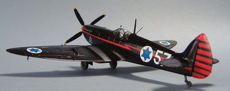
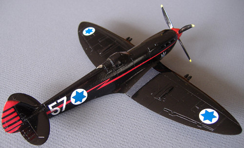
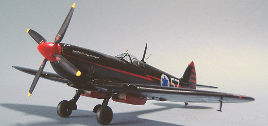
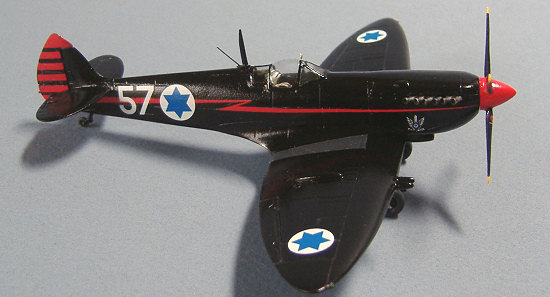
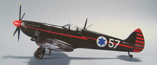
I had previously settled on the all-black IAF Spit with red lightning flash, as flown by Ezer Weizman in the late '70s. Further research on the Internet determined that this option was a non-operational hack, without armament, that is currently a flying museum example in Israel. (At the time, I did not realize that there were subtle paint differences exhibited over the years).
Although construction was not complete, I elected to paint the airframe a this stage. I have been using oil-based enamel since Humbrol was invented. It has always worked for me, whether brushed or sprayed. Aqueous acrylics hold an attraction, but I am not as comfortable working with them. The primary disadvantage to enamels is their drying time, and the fumes from spraying. If I can't find a particular colour, mixing is an option with commonly available primary colours. With this as background, I did not anticipate the disaster that occurred. Using a Pasche VL, fine tip, and suitably thinned black paint, I started to give an overall thin coat to the model. The paint wouldn't stick. It appeared to cover, then would form thick globules. I cut back on pressure, no improvement.
 The resultant mess was so
disheartening I left it for several days. The paint cured in that time, and I
was able to carefully sand the surface to smooth out the worst of the
irregularities. The same paint was tested on other surfaces with no problems
appearing. Gritting my teeth, I repeated the process; this time, the paint
adhered, although not as smoothly as I would have preferred. I must assume that
there was some oily or waxy material on the resin that alcohol did not remove,
causing the original lack of adhesion. In future, I will prep resin surfaces
with a spirit-based material, or use a lacquer-based primer.
The resultant mess was so
disheartening I left it for several days. The paint cured in that time, and I
was able to carefully sand the surface to smooth out the worst of the
irregularities. The same paint was tested on other surfaces with no problems
appearing. Gritting my teeth, I repeated the process; this time, the paint
adhered, although not as smoothly as I would have preferred. I must assume that
there was some oily or waxy material on the resin that alcohol did not remove,
causing the original lack of adhesion. In future, I will prep resin surfaces
with a spirit-based material, or use a lacquer-based primer.
I had several images gleaned from the Internet of the black Spitfire. Most of them, with the best detail, were of the recent airshow performer. I did not realize then that there were some significant differences in markings from the decals provided in the kit. CMR provides markings for two versions of TE554, both from the 1970's. Given the thoroughness of the rest of the model, I would assume these to be accurate. However, I was working to a later scheme, and quickly realized the problem. The fuselage markings are larger in the later version, and the red stripe a slightly different shape. Luckily, there are extra national markings of the correct size. I applied the red fuselage stripe first - it broke into several pieces, but lined up eventually. The white of the roundel is just slightly translucent, enough that the underlying stripe can be seen. I would suggest applying the roundel first, and then cutting the stripe to match. There is a unit emblem for the nose, what appears to be a winged sword on a circular red field. The references I was working to did not show the red field, so fine work with black paint and a brush bought that into conformity. A multitude of stencils are also available. However, being black, there was not much point applying them. The tail stripes went on with just a minor glitch. Positioning the starboard sided one, a tear occurred. I was able to salvage this with Future. Testors’ Decalset melded the decals to the model without problem. Other than my choice of subject, the decals, produced by Tally Ho, worked extremely well over the gloss paint.
| FINAL CONSTRUCTION |
The prop/spinner assembly was
tackled. Although I had carved a new blade for the single-piece unit, I was not
happy with the result, and thought the other blades a little slender. The five
part assembly had more authentic looking blades, so I decided to assemble that.
Four holes were drilled at appropriate spots in the spinner, the pieces
assembled with Microscale Liquitape, then made permanent with cyano. Definitely
an improvement. Red enamel was brushed directly onto the spinner, without
problem. The blades received a coat of black with yellow tips. Another coat of
red for the spinner, manufacturers' emblem decals applied to the blades, and it
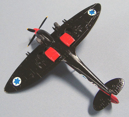
was done. Whilst the red paint was out, the underwing oil/glycol coolers were
given a c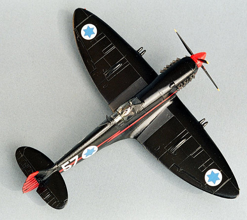 ouple of coats.
Undercarriage parts were assembled, then brushed black, as was the aerial mast,
the pitot, and the interior of the coolers. Metalizer exhaust was brushed on the
six exhausts. Wheels were given gloss black centres, with dark grey tires.
Silver was painted on the sliding parts of the u/c legs. Tiny nubs of plastic
became navigation lights on the wing leading edge, red and green.
ouple of coats.
Undercarriage parts were assembled, then brushed black, as was the aerial mast,
the pitot, and the interior of the coolers. Metalizer exhaust was brushed on the
six exhausts. Wheels were given gloss black centres, with dark grey tires.
Silver was painted on the sliding parts of the u/c legs. Tiny nubs of plastic
became navigation lights on the wing leading edge, red and green.
Now for the final fiddly bits. There is a p/e plate that fits between the fuselage and the aerial mast. This was curved to fit the fuselage contour. Paint was scrapped from the attachment point. Liquitape helped position the part, then cyano was applied. All seemed well. The mast was positioned - problem! The hole in the plate was not large enough for the mast attachment. The solution was to drill the hole larger. OK, except the drill bit bound in the plate, twisting it from its' attachment. Several tries later, with paint in the area becoming marred by the abuse, I gave up and butt jointed the mast. A UHF aerial from fine wire was added just aft of the main mast. The model was turned on its' back, and the main undercarriage assembly was glued in place, with reference to drawings and frequent checks on alignment. Then the tailwheel. Then the six pair of exhaust pipes. To my eye, the exhausts seem slightly overscale, but are remarkably detailed, with hollow ends. Under the port wing, a tiny pitot is glued. After the prop/spinner assembly is mounted on the fuselage, all that is left is the underwing radiators and covers. First, small blocks are glued to depressions under the wings. To these, photoetch front and rear grills are attached. Ensuring handedness is recommended; it is hinted at in the instructions, but not explicit. Then the covers, this time marked on the inside with a Left and a Right. I found that the grills were too large for the inside of the covers - too late, as they were already glued to the mounting blocks. Some surgery with scissors and a knife reduced the height of the grills, and then the covers slid into place.
The high gloss finish needed toning down slightly to reduce the sheen. Testors’ Metalizer Sealer was sprayed overall. This also blended the decals a little better. The masking was removed from the canopy. Very little touch-up was required, unusual on my projects.
| CONCLUSIONS |
The accuracy and completeness
of this resin and photoetch 1/72 kit can be faulted on very few counts, the
primary ones being cost, availability, and the fact it is not injection moulded
plastic. CMR seems to be issuing as
 complete a range of Spitfires
and Seafires as possible in 1/72; mainstream plastic manufacturers, please take
note. This can be a demanding assembly project. I confess to little patience
with parts that are not visible, or that do not contribute to the finished
appearance of a model. However, to those modellers with the skills and patience
to handle miniature pieces of resin and etched metal, this can be a challenge,
and some will turn this kit into a masterpiece. I consider CMR's version of the
Spitfire in this scale to be definitive in shape and detail, and hope that
injection kits will appear to duplicate that accuracy. Recommended to those with
multi-media skills, and/or those demanding the finest rendition of a Spitfire
IXE in 1/72 scale.
complete a range of Spitfires
and Seafires as possible in 1/72; mainstream plastic manufacturers, please take
note. This can be a demanding assembly project. I confess to little patience
with parts that are not visible, or that do not contribute to the finished
appearance of a model. However, to those modellers with the skills and patience
to handle miniature pieces of resin and etched metal, this can be a challenge,
and some will turn this kit into a masterpiece. I consider CMR's version of the
Spitfire in this scale to be definitive in shape and detail, and hope that
injection kits will appear to duplicate that accuracy. Recommended to those with
multi-media skills, and/or those demanding the finest rendition of a Spitfire
IXE in 1/72 scale.
Many thanks to Terry Higgins for his help with the cockpit, and introduction to various advanced modelling techniques. Amazed thanks to Scott van Aken for parting with this little gem.
| REFERENCES |
Numerous Internet sites, including:
http://www.1000pictures.com/aircraft/spitfire/index.htm
(Google: Spitfire IX; black Spitfire; Israeli Air force)
Print, including but not limited to:
1/72 line drawings by D.H. Cooksey ( Aeromodeller and Aircraft Archive, vol. 1)
Spitfire - the History by Morgan & Shacklady
Spitfire, the story of a famous fighter by B. Robertson
May 2007
My thanks to
 Czech Master Resin for providing the review copy.
If you would like your product reviewed fairly and quickly by a site that has nearly 350,000 visitors a month, please contact me or see other details in the Note to Contributors.