Valom 1/72 Ablemarle V
| KIT #: | ? |
| PRICE: | £25.00 MSRP |
| DECALS: | One option |
| REVIEWER: | Carmel J. Attard |
| NOTES: | Short run with etched parts. |
| HISTORY |
The Armstrong Whitworth AW41 Albemarle was a British twin engine transport aircraft that entered service during WWII. Originally it was designed as a medium bomber of wood and metal construction so that it could be built by manufacturers outside the aircraft industry. Large parts were designed of steel to conserve aluminium which was in short supply. The fuselage was welded from steel tubes and covered with plywood. The wings were wooden with steel beams. The tail and controlling areas had canvas surfaces. This had a negative effect on performance. Consequently the entire production run of 600 Albemarles were built by AW Hawksley Ltd. of Gloucester. The original bomber design required a crew of 6 including two gunners, one on a 4-gun .303 Brownings dorsal turret and one in a twin gun ventral turret. The first 32 aircraft designated the Mk1 Series 1. Production in this configuration never operated in a bomber role but, instead being converted for general and special transport duties, paratroops transport where it could hold up to ten troopers, and glider towing. The Albemarle design included a retractable nose wheel undercarriage in addition to a semi concealed tail-wheel, making it to be the first of type with this feature to enter RAF service. Two Bristol Hercules XI air cooled 14-cylinder two-row radial engines each rated at 1590 hp.
The Albemarle took part in many of
the British Airborne Operations such as the invasion of Sicily and Normandy and
the assault on Arnhem during operation Market Garden. The first squadron to
operate the Albemarle was 295 in January 1943 at an airfield in Hanwell, a
village in Oxfordshire. Other squadrons to be equipped with this aircr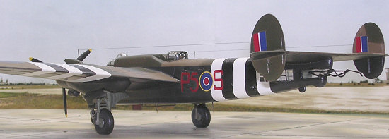 aft
were 296, 297 and 570 Squadrons while other squadrons operated small numbers of
the aircraft.
aft
were 296, 297 and 570 Squadrons while other squadrons operated small numbers of
the aircraft.
In spite of lack of information and that little is known of the Albemarle it will be interesting to note the role it has played in its first participation as an invading force. In the afternoon of 9th of July 1943 the armada of some 2,000 vessels began moving northwards from the assembly area on the shores of Tunisia in operation ‘Husky’. The hundreds of landing crafts and other vessels made their way to the beaches carrying 16,000 troops of the British 8th Army and the US 7th Army. The weather was poor but the element of surprise was complete. The western part of the force was covered by the squadrons of the Coastal Air Force, and the eastern part by the Eastern Air Command units. As the convoys approached the southern Sicilian coastline in the early hours of the 10th of July, transport aircraft carrying the airborne forces had already taken off from Kairouan area of Tunisia, The main force of C-47s were to drop the US 82nd Airborne Division in the Gela-Licata area. The 1stAir Landing Brigade of the British1st Airborne Division was to be transported in Gliders near Syracuse and seize the Porte Grande Bridge to the south of the town. The 1,200 men of the Air Landing Brigade entrained in 127 Wacos and 10 Horsa, which were towed by 102 C-47s, 28 Albemarle glider-tugs of 295 Squadron detachment and 7 Halifaxes. Some sources quote 108 Dakotas and 22 Albemarle and 7 Halifaxes each towing gliders packed with troops. These passed Dellimara Point which is the southern most point on the island of Malta at an exactly 21.20 hours on the 9th of July at altitude of 250-350 feet. An escort of Hurricanes night intruders from the 73 Squadron detachment on Malta joined in. These were to strafe any searchlights which might be encountered.
 Resistance was light as the
axis had not been aware of the planned location of the assault. The 85 mile long
stretch of landing craft off the Sicilian beaches was a prime target for the
Luftwaffe forces in Sicily. The airfield at Xewkija in Gozo was used by the
USAAF. However the bulk of aircraft used in the invasion did not use Malta
Airfields. The Malta based aircraft gave protection from a few moments after
dawn with five Squadrons of Malta-based Spitfires over beach heads of Avola,
Pochino and Scogliatti. 57 enemy fighters were sighted during nearly 1100 allied
sorties. The enemy concentrated in trying to repel the bomber forces from North
Africa. On the 12th of July a firm foothold had been established in
Sicily.
Resistance was light as the
axis had not been aware of the planned location of the assault. The 85 mile long
stretch of landing craft off the Sicilian beaches was a prime target for the
Luftwaffe forces in Sicily. The airfield at Xewkija in Gozo was used by the
USAAF. However the bulk of aircraft used in the invasion did not use Malta
Airfields. The Malta based aircraft gave protection from a few moments after
dawn with five Squadrons of Malta-based Spitfires over beach heads of Avola,
Pochino and Scogliatti. 57 enemy fighters were sighted during nearly 1100 allied
sorties. The enemy concentrated in trying to repel the bomber forces from North
Africa. On the 12th of July a firm foothold had been established in
Sicily.
Regular transportation of freight from UK to Malta became a feature throughout the war years. Freight bearing wooden floors were installed in two Liberators transport versions. The initial target was to be 35 tons of freight per month. The nucleus developed into a considerable enterprise as time went by and by August 1943 was supplemented by a Hendon to Luqa airfield service flown initially by Almemarles and later by Dakotas.
In 1943 fourteen Albemarles were transported to the Soviet Union as a gift of the British Royal Family.
| THE KIT |
The Valom kit of the Albemarle has been a very welcome
release as it is the first time that it is available as an injection moulded
plastic kit form. There were two previous releases of the Albemarle at a scale
of 1/72 and in cases, Contrail, and Hallam-Vac, the kits were vac form type and
are hard to find these days. The Valom kit is a short run multi media kit
moulded in grey plastic. This is one of the larger kits in the range so far and
a lot of effort has been put into it which certainly makes it all the more
welcome. Being 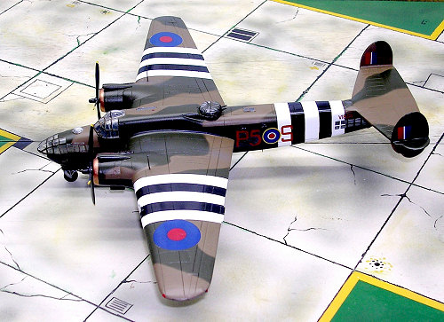 a short run
type the runners are on the thick side and one has to be careful to remove the
parts from the sprue attachment point to ensure not to cause damage. This was
done by separating the parts using an exacto saw. The kit parts also needed
general cleaning from fins and flashes.
a short run
type the runners are on the thick side and one has to be careful to remove the
parts from the sprue attachment point to ensure not to cause damage. This was
done by separating the parts using an exacto saw. The kit parts also needed
general cleaning from fins and flashes.
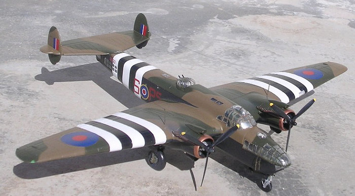
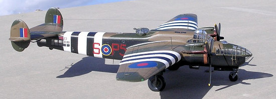
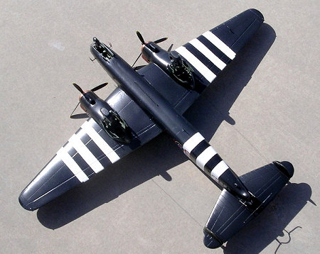
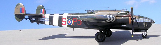
The kit contains 47 parts in grey plastic, 20 parts in clear plastic, 28 cream coloured resin and a brass fret for fine detail parts. A correctly registered decal covers one aircraft scheme which is in standard war camouflage and carries Normandy type black and white invasion stripes. The assembly of the kit is depicted in 18 stage instruction book which has history of the aircraft, plan view of parts for quick reference, clear illustrations that makes the assembly an easy task. There is also a five view colour drawing which proves to be helpful to refer to during the painting stage. This has minor inaccuracies if carefully studied. For instance the front elevation shows the exhaust manifold to fit on the starboard side i.e. correct as they should be whereas in the plan views of both upper and lower surfaces these are shown on the side facing the fuselage in each case. This is also incorrectly shown in stage 13.The demarcation line of camouflage on the engine nacelle can also be confusing as two views show this differently.
The first stages deal with sub assemblies of the instrument
panel that contains clear plastic print with gauges, series of levers and brass
etch panel which is painted prior to assembly. The cockpit sub assembly is very
well detailed with pilot and co-pilot seat as well as crew seat in the nose
area. More levers and rear and fron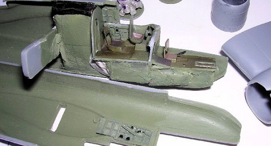 t
bulkheads complete the cockpit. I painted interior cockpit green and all details
with touches of black. I found that in order to fit the floor correctly, this
should have 1mm removed from the right edge to allow the fuselage sides to
close. The cockpit side resin panelling should be well reduced in section and I
have found that these should be best attached to the respective places after the
cockpit floor and bulkheads are in place and not before as indicated in stage
10. It will be noticed that the panels R1 and R2 should also be trimmed at
bottom to fit in place.
t
bulkheads complete the cockpit. I painted interior cockpit green and all details
with touches of black. I found that in order to fit the floor correctly, this
should have 1mm removed from the right edge to allow the fuselage sides to
close. The cockpit side resin panelling should be well reduced in section and I
have found that these should be best attached to the respective places after the
cockpit floor and bulkheads are in place and not before as indicated in stage
10. It will be noticed that the panels R1 and R2 should also be trimmed at
bottom to fit in place.
All these items are fixed in place before the two halves are joined. Further more since we are dealing with a kit with tricycle undercarriage which is rear heavy we need to add a good amount of weight to every space we afford: under the nose floor; at the space left on each side when the nose undercarriage box is in place; and also in a compartment right behind the cockpit bulkhead. I found that it was best to construct another bulkhead so that the weight added is retained between the two bulkheads without fear of breaking loose with time. In doing so the weight added is painted matt black so that this will not show from the cockpit open door. In order to play safe I also added round flat lead pieces at the compartment behind the radial engine resin part. Other items that needed slight trimming were the rear elongated window clear pieces. I did not fit the smaller rectangular and round windows that go to the fuselage sides as these were quite small and in that case could permit using Kristal Kleer. Valom must be praised at the manner they provided a cross beam which would keep the wings fitted at the correct angle of dihedral. The interior turret bucket and seat were also fitted to one side of fuselage before this is closed to form a complete fuselage.
 Turning
to the wings assembly, I have fixed pieces of sprue from same kit to the
interior of the leading edge of lower wing. This was going to self align the two
wing parts when joined together at a later stage. Before doing so one should
attend to fitting the undercarriage well roof, Parts 8 and 29, at the correct
place. This is an important step because as the wings have a dihedral the
undercarriage legs should be perpendicular to the floor. To arrive to this
position the well roof has to be fixed at an angle inside the engine nacelle.
Unfortunately this is not clearly indicated in the instructions. A trial dry
fitting will be helpful. Once the nacelle roof is secure and fixed in place the
wing halves are joined together. The rest of kit assembly of tail plane, fins
etc went smoothly.
Turning
to the wings assembly, I have fixed pieces of sprue from same kit to the
interior of the leading edge of lower wing. This was going to self align the two
wing parts when joined together at a later stage. Before doing so one should
attend to fitting the undercarriage well roof, Parts 8 and 29, at the correct
place. This is an important step because as the wings have a dihedral the
undercarriage legs should be perpendicular to the floor. To arrive to this
position the well roof has to be fixed at an angle inside the engine nacelle.
Unfortunately this is not clearly indicated in the instructions. A trial dry
fitting will be helpful. Once the nacelle roof is secure and fixed in place the
wing halves are joined together. The rest of kit assembly of tail plane, fins
etc went smoothly.
Among other items that need improvement is the front wheel mudguard which is not long enough as it is shown in drawing at Stage7. I also added a whip aerial at a place just aft of the bomb bay area. An interesting observation about this aircraft was the offset position of the upper turret towards the port side and this is very well reproduced in the kit Finally the nose side antennae should go to both sides of the nose as indicated in stages 16 and 18 and not as shown on one side as depicted in the colour 5view drawing. Fitting of parts left few areas that needed putty and sanding, mainly at the wing roots and upper fuselage joining line. Masking the cockpit and window clear parts was time consuming but a worthwhile effort.
| CONCLUSIONS |
 In
general careful study was essential before I went about building the Albemarle
model. This is a short run kit and again not the type to go rushing about in
building it. It also requires a certain amount of experience but in the end it
results into a fairly large pleasing model. One starts to wonder why there was
no injection moulded kit of the type before in view of the part played during
the war and that so many were built and served in the RAF even for a time after
the war ended. This is certainly the kit to go in collections favouring the
subject of airborne operations. The Horsa, Waco, and hotspur gliders and C-47
Sterling, and Albemarle as glider tow aircraft will make an interesting section
of any collection in its respects.
In
general careful study was essential before I went about building the Albemarle
model. This is a short run kit and again not the type to go rushing about in
building it. It also requires a certain amount of experience but in the end it
results into a fairly large pleasing model. One starts to wonder why there was
no injection moulded kit of the type before in view of the part played during
the war and that so many were built and served in the RAF even for a time after
the war ended. This is certainly the kit to go in collections favouring the
subject of airborne operations. The Horsa, Waco, and hotspur gliders and C-47
Sterling, and Albemarle as glider tow aircraft will make an interesting section
of any collection in its respects.
| REFERENCES |
Mediterranean Air War Vol II by Christopher F. Shores
Military Aviation in Malta G.C. by John F Hamlin
November 2006
Copyright ModelingMadness.com
If you would like your product reviewed fairly and fairly quickly, please contact the editor or see other details in the Note to Contributors.