
Special Hobby 1/48 Bugatti 100
| KIT #: | 48219 |
| PRICE: | $40.00 |
| DECALS: | Instrument panel |
| REVIEWER: | John Summerford |
| NOTES: |
| HISTORY |
Edited from the EAA Aviation Museum and Wikipedia
Say the name Bugatti and race cars should come to mind. Beautiful, fast, and sleek, the Bugatti racers dominated the European racing scene during the 1920s and ’30s. But the company also had an aviation connection, and a unique one at that — the Bugatti Model 100P racer, the sole example of which is on permanent display at the EAA Aviation Museum.
Ettore Bugatti’s interest in aircraft developed after WWI and his great successes in automobile racing. He decided to take the Germans head-on in the Deutsch de La Muerte Cup Race. This was an aircraft race equivalent to the Thompson Trophy Race held in the United States. With this desire to beat the Germans, he hired Louis de Monge to design an airframe. The original concept was for a single-engine aircraft, but it was later changed to accommodate two modified Bugatti model 50B straight-eight engines to challenge the world airplane speed record.
 Construction
of the aircraft was undertaken on the second floor of a furniture factory in
Paris. The French government was aware of the advanced design and Bugatti
received a contract for a light pursuit plane designated as the Model 110P based
on the Model 100P racer. Development started in 1938, too late for that year’s
race and the outbreak of WWII halted racing. The futuristic airplane never took
to the air.
Construction
of the aircraft was undertaken on the second floor of a furniture factory in
Paris. The French government was aware of the advanced design and Bugatti
received a contract for a light pursuit plane designated as the Model 110P based
on the Model 100P racer. Development started in 1938, too late for that year’s
race and the outbreak of WWII halted racing. The futuristic airplane never took
to the air.
When the Germans neared the French capital in June 1940, it was decided to move the aircraft from its Paris location. As the plane was not complete, it was lowered from a second-story window of the factory and taken into the French countryside. There, tucked away in a barn, the airframe resided for almost 30 years.
After passing through several owners, the aircraft was donated to the EAA Aviation Museum in 1996 and was on display shortly thereafter. This example of unconventional forward thinking is inspiring even today.
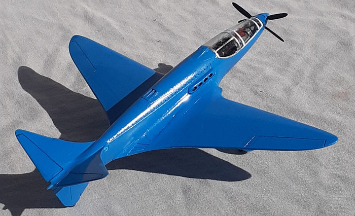
The Model 100 had an unusual inboard mounted twin engine arrangement driving forward-mounted contra-rotating propellers through driveshafts. It also featured a 120-degree v-tail arrangement and retractable landing gear. The construction was mostly of wood, with sandwiched layers of balsa and hardwoods, including tulipwood stringers covered with doped fabric.
Even though the original airplane never flew, the design finally did. Avid pilot and builder Scotty Wilson, EAA 572551, and his team spent seven years and more than 10,000 man-hours painstakingly creating a reproduction of the 100P, which first flew on August 19, 2015. Tragically, Wilson was killed and the airplane destroyed in a crash on its third flight.
| THE KIT |
A single bag holds two sprues of styrene totaling 54 parts, A bag of five resin parts, one bagged clear part, and a bagged fret of nine photo-etch parts, for a total of 69 parts. The 12-page instruction booklet is printed in color on glossy paper. The first page has a history in Czech and English. Page two has parts maps and color references keyed to Humbrol and Gunze paints. Pages 3-7 hold the illustrated assembly sequence of 21 steps. The next two pages show two paint schemes and the final three pages contain advertisements for other Special Hobby and CMK products.
| CONSTRUCTION |
 Assembly
starts with gluing the two-piece gear box, prop shaft, and front cockpit
bulkhead together. The right cockpit half is built up next. After that, I
deviated from the instructions by taping the fuselage halves together and placed
the rear end of left drive shaft cover against rear bulkhead and glued it to the
fuselage half. The interior and seat parts were then painted red.
Assembly
starts with gluing the two-piece gear box, prop shaft, and front cockpit
bulkhead together. The right cockpit half is built up next. After that, I
deviated from the instructions by taping the fuselage halves together and placed
the rear end of left drive shaft cover against rear bulkhead and glued it to the
fuselage half. The interior and seat parts were then painted red.
Circling back to steps 4 and 5, the seat and harness were installed. The frame for the seat pan is too wide. That wasn’t discovered until the halves were closed up and a sideways tilt became noticeable. Fortunately, it is difficult to observe with the canopy in place. The subassembly from step 1 was installed, along with the rest of cockpit pieces and the fuselage halves mated. Top and bottom seams were filled and sanded smooth.
Before assembling the wings, the wheel wells must be painted a faux wood effect. The resin wells are 3-D printed and require a coat of primer first. Special Hobby provides positive locating ridges on the lower wing part for the wells and it was easy to glue them in place. Test fitting the upper pieces revealed that a lot of material needed to be removed from the roof of the wells to achieve a good fit.
While the glue was curing on the wings, the canopy was masked and attached. Some gentle clamp pressure was used to keep it in place while its glue set.
It was disappointing to discover the gaps in the wing to fuselage joints. They were addressed with shims and filler.
 Attaching
the tail surfaces was more difficult than it should have been. Special Hobby
missed an opportunity chamfer the mating surfaces so that, on the fuselage, the
chamfer slopes up and in, and the stabilizers down and out. They would have
dropped into place. Instead, with the left stabilizer too long in span, removing
enough material to achieve proper alignment was a challenge. The instructions
call for the tail “cone” to be added to the tail subassembly before attaching to
the fuselage. Given the work of aligning stabilizers/elevators, that was
attached afterword and all the tail seams were filled and sanded.
Attaching
the tail surfaces was more difficult than it should have been. Special Hobby
missed an opportunity chamfer the mating surfaces so that, on the fuselage, the
chamfer slopes up and in, and the stabilizers down and out. They would have
dropped into place. Instead, with the left stabilizer too long in span, removing
enough material to achieve proper alignment was a challenge. The instructions
call for the tail “cone” to be added to the tail subassembly before attaching to
the fuselage. Given the work of aligning stabilizers/elevators, that was
attached afterword and all the tail seams were filled and sanded.
Additional work was needed on the intake vanes on the leading edges of the tail surfaces. Most of the vanes stood proud and had to be filed down and cleaned up.
It wasn’t until the exhaust pipe shrouds were installed that I realized how the engines in the racer were laid out. They are not in tandem, but staggered, hence the two driveshafts.
The counter-rotating prop assembly was fiddly due to each blade having to be glued to the backing plate. Yes, they are keyed so that they are aligned in the right direction. When that assembly done, the wheel wells were filled with foam packing material the model was ready for paint
| COLORS & MARKINGS |
 Stating at
the canopy, Alclad II clear base was sprayed on, then White Aluminum on the aft
section. After that cured, the front section was painted white.
Stating at
the canopy, Alclad II clear base was sprayed on, then White Aluminum on the aft
section. After that cured, the front section was painted white.
Establishing the correct hue of blue for the airframe is difficult. The color call out in the instructions is too dark. The illustration on the cover is more accurate. The aircraft sits in dimly lit gallery so the photos that I was able to find online used a flash, which results in multiple hues that depend on how far away the light was. A custom mix of gloss blue and gloss white enamel was airbrushed on.
A wash of black was brushed along the hinge lines of the ailerons, elevators, and exhaust outlets to add some detail.
Prop logo decals were sources form the decal dungeon. Last tasks were installing the landing gear, which was straight forward, if a bit fiddly, and finally gluing on the prop finished the build.
| CONCLUSIONS |
This is an interesting one-off. The cockpit layout of this aircraft makes for a fussy start. Gaps in the major seams call for developed sculpting skills, tools, supplies, and time. By putting in the extra work though, a nifty model will result.
29 April 2024
Copyright ModelingMadness.com. All rights reserved. No reproduction in part or in whole without express permission.
If you would like your product reviewed fairly and fairly quickly, please contact the editor or see other details in the Note to Contributors.